
My frequent readers will know that I have had previous spinner issues. Mainly the main bulkhead would develop cracks around the 4 mounting bolts that attached the bulkhead to the propeller hub itself. I knew the spinner dome may have been the culprit, but I thought I could make a rear bulkhead strong enough to withstand any vibration caused by the dome. Well, that failed. My last version failed after 25 hours!
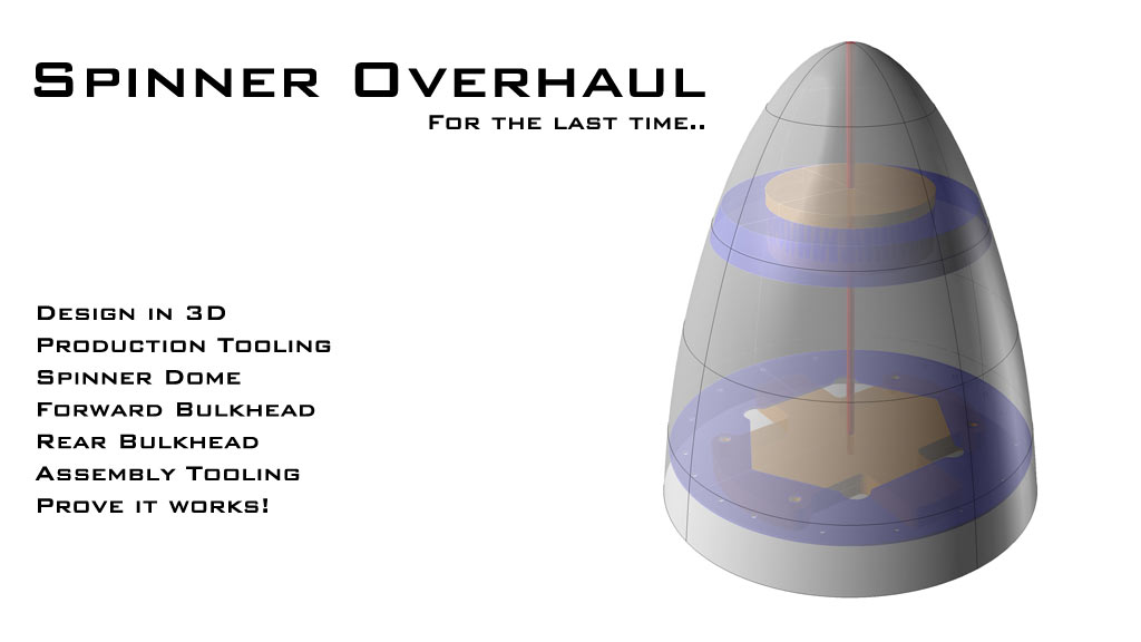
So, during my major firewall forward upgrade I put the spinner high on the priority list. I set a few goals for the project.
- Replace Spinner Dome
- Make a Forward Bulkhead
- Make a Rear Bulkhead out of Carbon
Spinner Dome
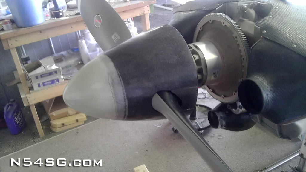
I started by ordering a new spinner dome from Lancair. Well, what I got isn’t exactly up to my standards I guess. It is a fiberglass part with a layer of carbon wrapped around the bottom half. The part looked fine, but.. I put the spinner on a turn table to see how straight it was. It turns out that it had a wider section in the middle. Hard to explain. The tip was straight, but while spinning you could see and feel the middle of the part getting thicker and thinner as it spun. I can only assume their mold is old and not exactly round anymore. It has probably been making 320/360 spinners for a number of years.. Back to the drawing board then. I am going to need to build my own spinner mold that is truly round so I can produce a perfect spinner dome.


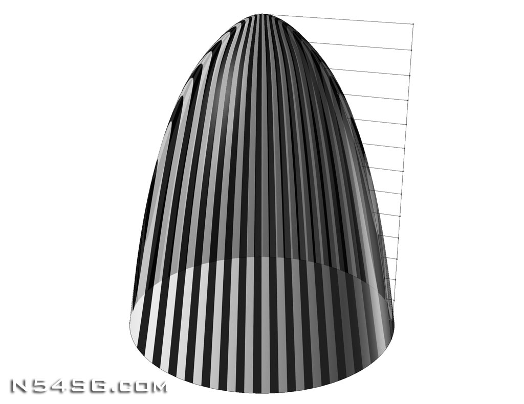
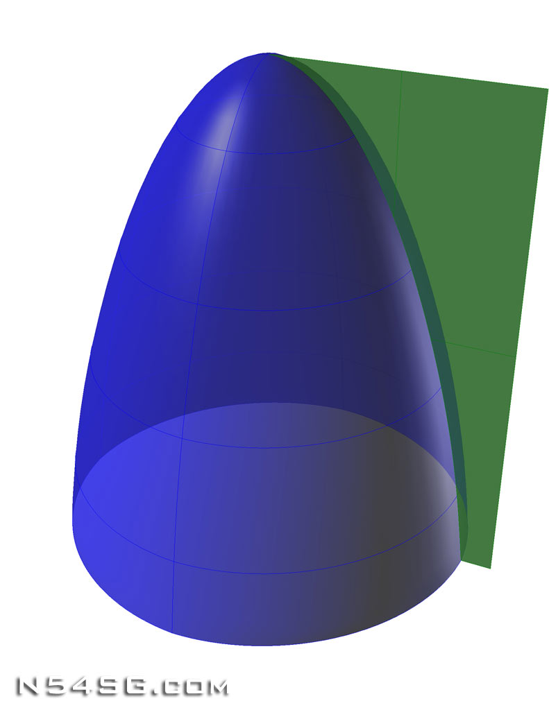
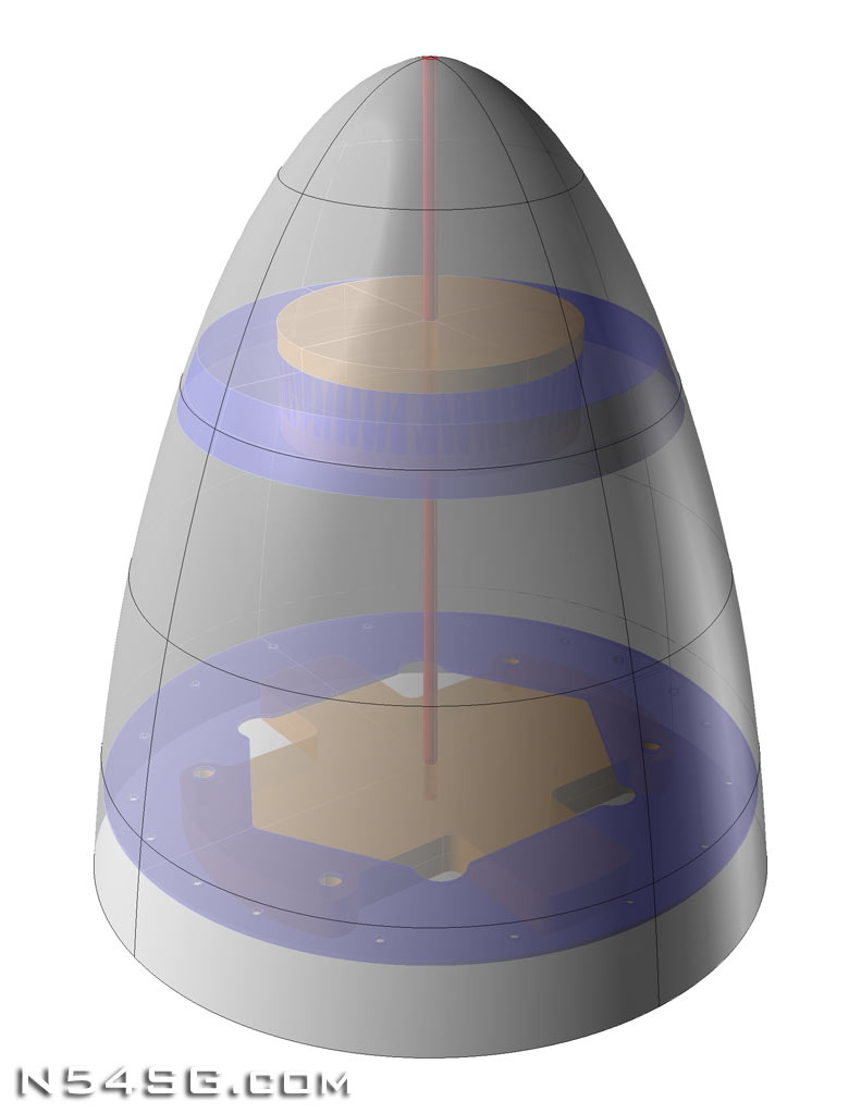
In the end I figured the only way to do this was with CAD (Computer Aided Drafting) and some CNC’d tools. Turns out that is a big deal. I started by lofting the spinner in 3D. I used a set of data points based on the current spinner I had, only modifying them a small amount for a little bit better looking shape.
Now that I had the 3D shape, I could take a cross section to define a curve from the Z axis. This is what a CNC lathe would use to cut the plug shape to be used to make the mold. So all the work, for a single curve.
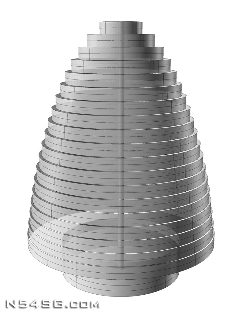
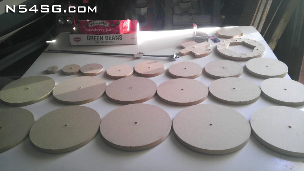
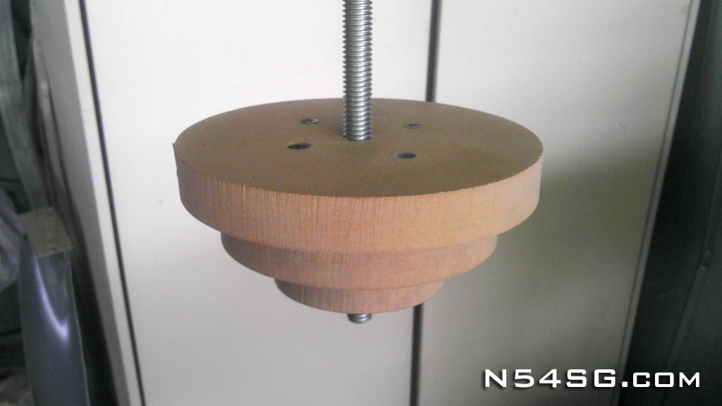
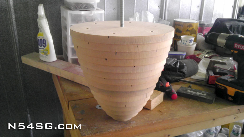
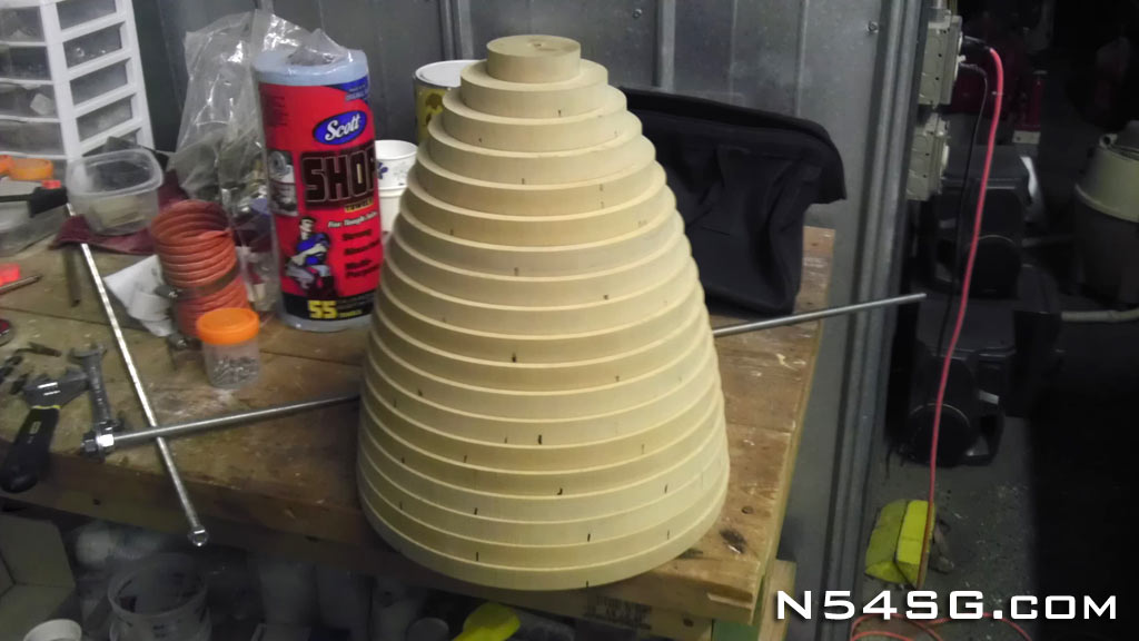
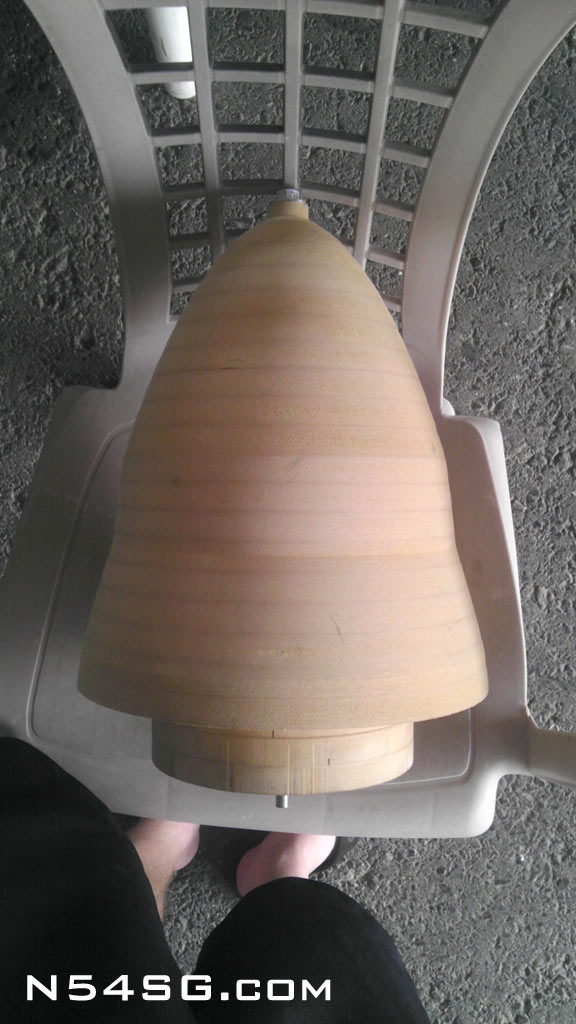
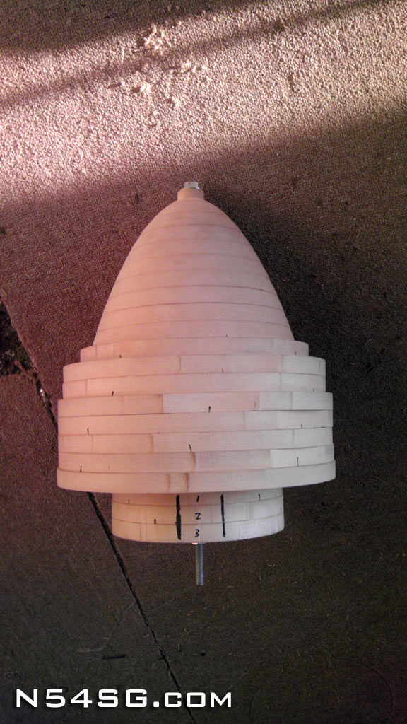
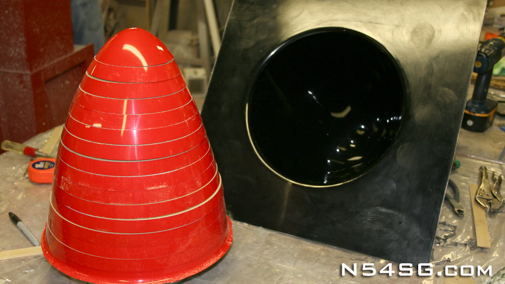
Next I tried to figure out what to make the plug out of. I ended up using 3/4″ MDF because it was cheap, easy to cut, and dense enough for what I was doing. Looking back, I probably would have used something harder, but I don’t really know what that would be. I’m open to suggestions.. 🙂 Anyway, I modeled the stack of MDF in 3D, extracting a set of diameters to assemble the basic shape. The key is that all these circles had a center hole to grantee it remains straight. I had the MDF water jet cut based on a CAD file of all the circles. Eh, probably overkill looking back. Any out of round issues would have been cut down on the lathe. Regardless, with all the circles I start to stack them from the tip of the spinner down, using countersunk screws to attached each layer to the next with a 3/8″ all thread center. Then I had this massive block of wood that resembles the shape and could be clamped in a CNC lathe.


The first try didn’t work out so well. The programmer made a mistake in the data entry and the machine cut the first half of the spinner incorrect. I got to hear a lot of funny jokes about what it looked like. Think up your own, and do share! haha So, I had to rebuild half of the plug so it could be cut again. The end result is what I expected the first go around.


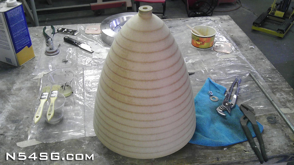
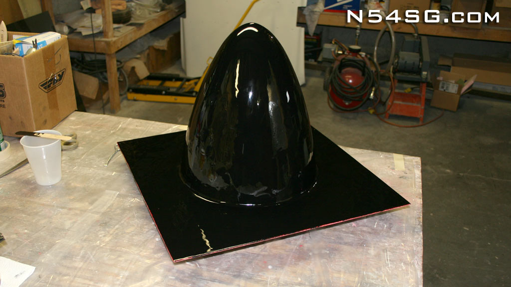
Next the wood plug was body worked and a surface coat was applied. The top nipple left from the tooling clamp was cut off and manually worked out, and it was attached to a flat base so the mold would have a nice flange on it. Turned out great!
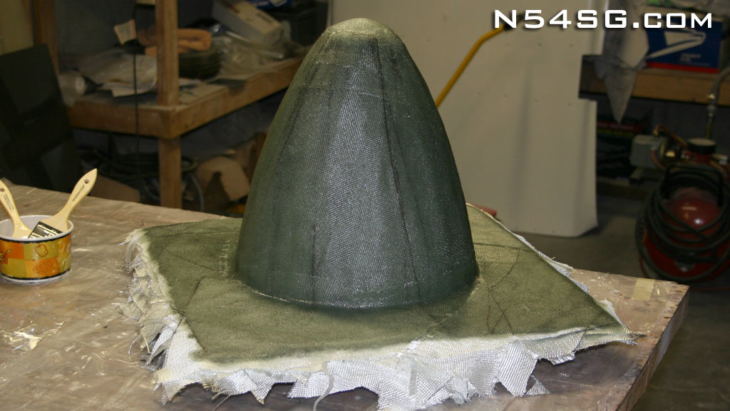
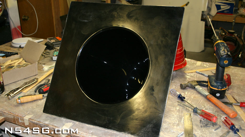
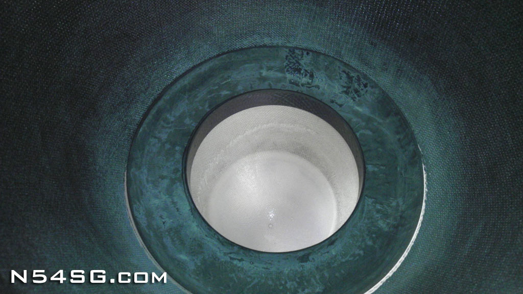
Now with a completed plug, the mold could be made. First the mold surface coat was applied. (The black stuff) Then, I think it took all 50 yards of tooling cloth to cover the plug with 14 layers. I know it is only 2 pictures, but that was a serious day of work, and a lot of resin. The end result after it cured and the plug was removed is a great looking mold!


Bulkheads
With my 3D model I had known shapes to create the forward and aft bulkheads, with a twist. We’ll start with the aft or rear bulkhead. The problem with making this in carbon would be it would required another mold that had to be perfectly round, if done the conventional way with a lip for the screws. I started thinking, why try and put this flange on the bulkhead, why not put it on the spinner and screw the bulkhead to the spinner instead? Well, that was a damn good idea. It does two things for me. One, the rear bulkhead is now 2D, or flat. Much more simple. Two, this design would make the spinner appear to be screw less! How cool is that!
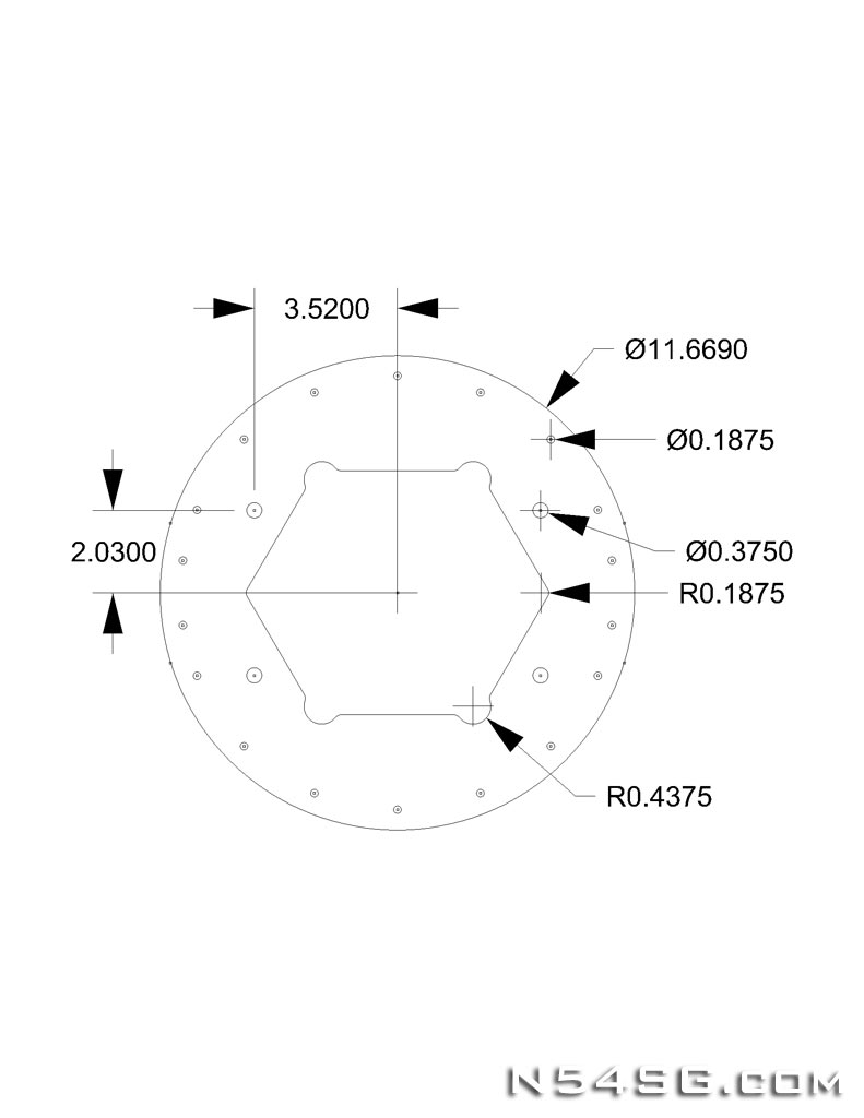
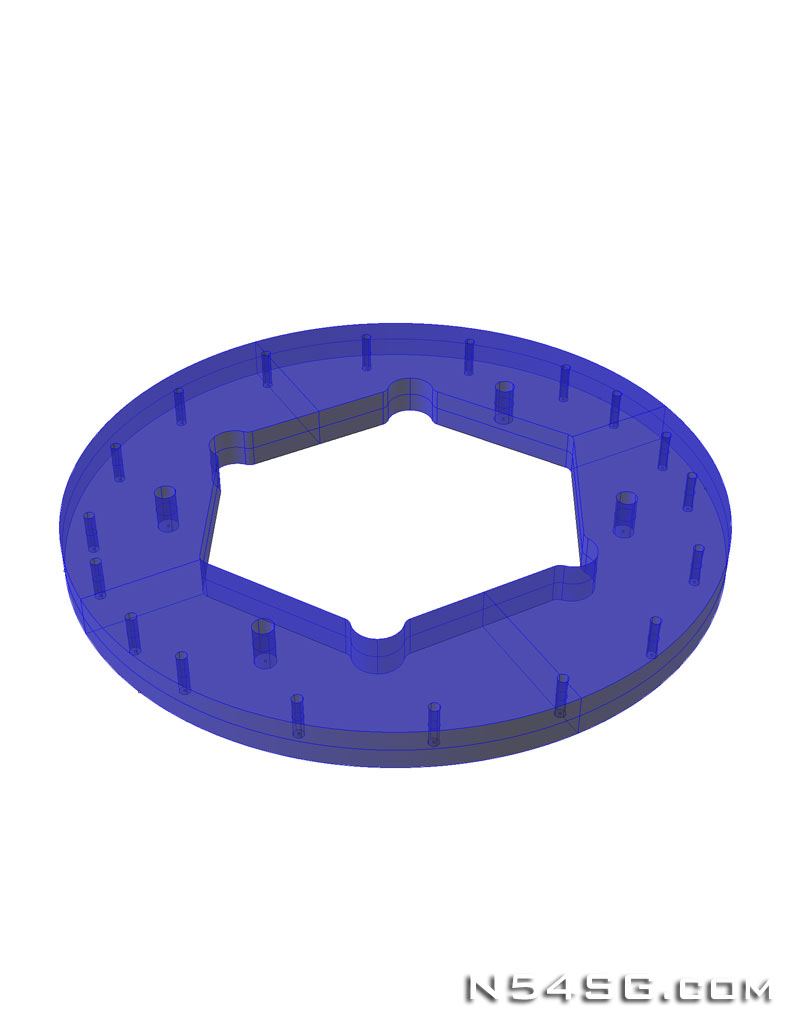
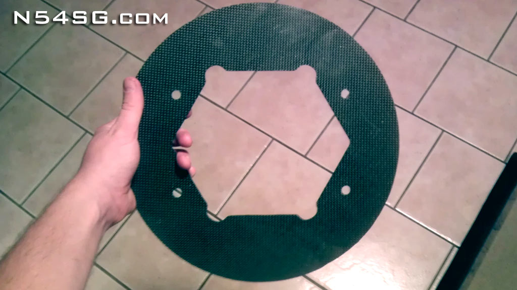
So in my CAD program I designed the rear bulkhead based on the mounting bolts for the hub, the rather odd hole in the center so it would fit over the hub and the spinner screw locations. I was able to figure the outside diameter based on the inside diameter of the spinner and the mounting bolt location on the hub. Hard to explain I guess. I also had to stagger the spinner screws to accommodate the spacers that install behind the propeller blade itself. The tool would be a mirror image of the part, as I plan on using a router to trace the tool and cut the bulkhead out of a cured 12 layer thick carbon sheet.


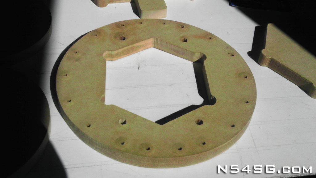
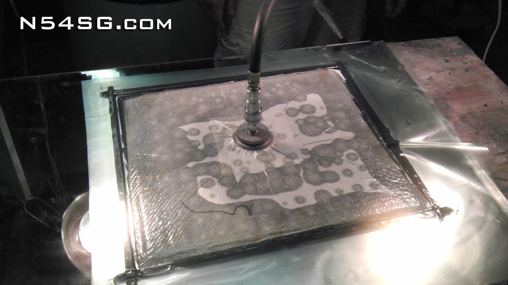
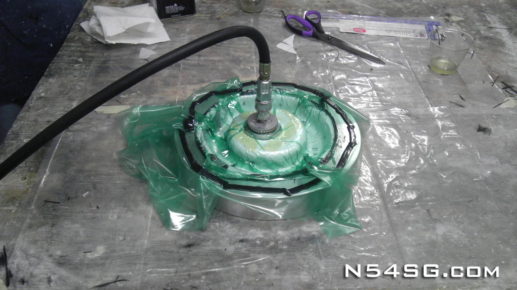
To make the solid carbon sheet, 12 layers of 282 carbon were cured under vacuum on a mirror to assure a flat and great looking part. Then with the cured sheet bolted to my wood template, I simply traced the template with a router. The bit had a bearing to travel along the template. I also drilled all the holes guaranteeing a totally symmetrical (and therefore balanced) part.
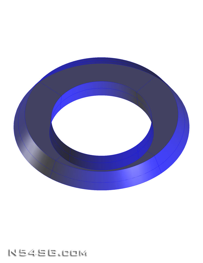
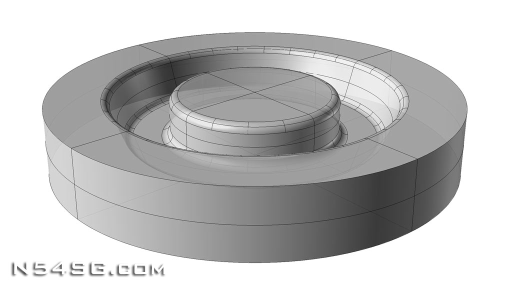
Next I started to work on the forward bulkhead design. The tricky part about the forward bulkhead is that the diameter of the dome varies depending on how the rear bulkhead is mounted to the hub. And, the normal way to do it doesn’t allow any room for forward and aft movement of the spinner. (To set cowling gap for example) So, I designed the forward bulkhead to slip over the piston dome on the Hartzell prop. This would allow for the forward and aft movement, and allow for a fixed diameter part. The tool would be more complicated, as it is actually a mold for a 3 dimensional part, with a surface that permanently bonds to the inside of the spinner dome.


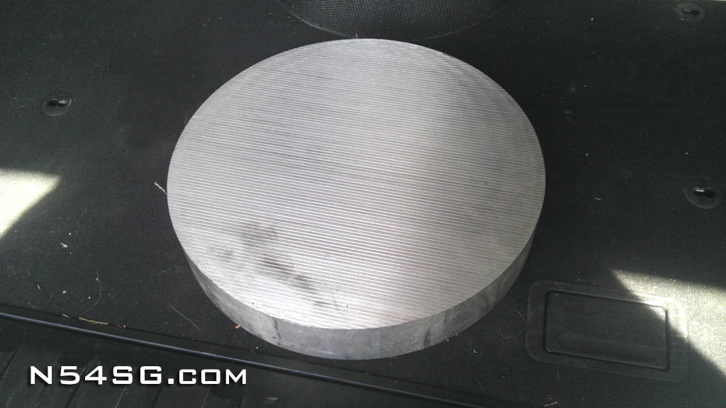
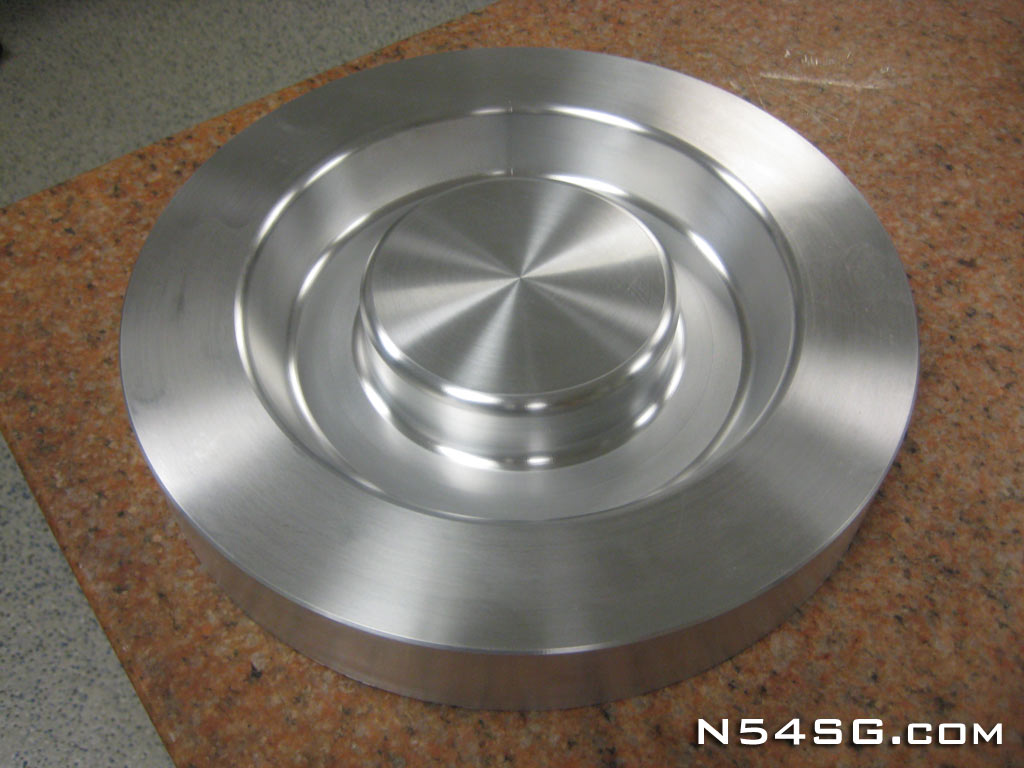
I went to a local metal supplier and got what they call a biscuit. That being a 2″ long, 12″ diameter, 6061 T6 aluminum. Yeah, it weighs more than you think, but this would mean a nice, solid, long lasting mold for this part. I took that to a fellow EAA Chapter 91 member who was able to CNC the mold based on my 3D model. Looks great doesn’t it!!!


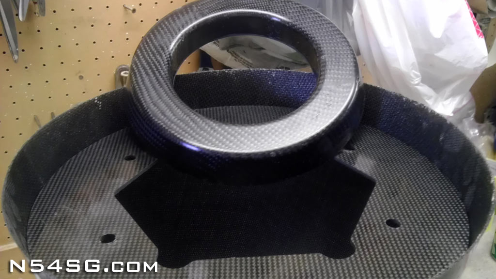
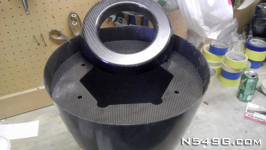
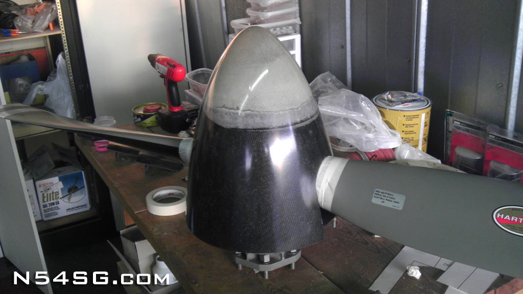
With this beautiful mold done, 5 layers of carbon were cured under vacuum to make the first part. In the end, I would make it much thinner next time. 3 layers would be plenty. Below are a few pics of both bulkheads with the stock spinner. Notice how the forward bulkhead slips over the Hartzell prop, allowing 2.5″ forward and aft movement.


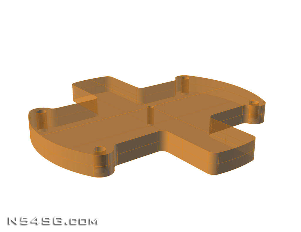
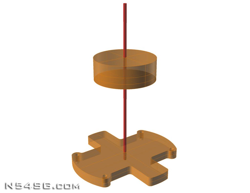
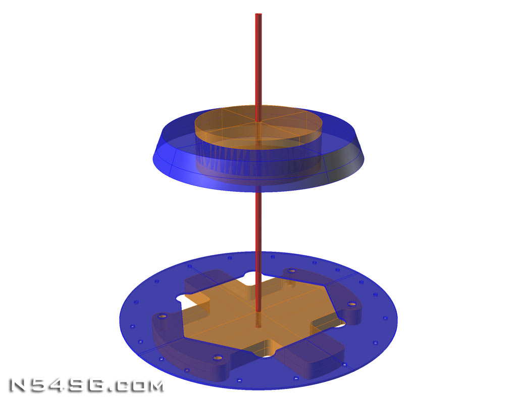
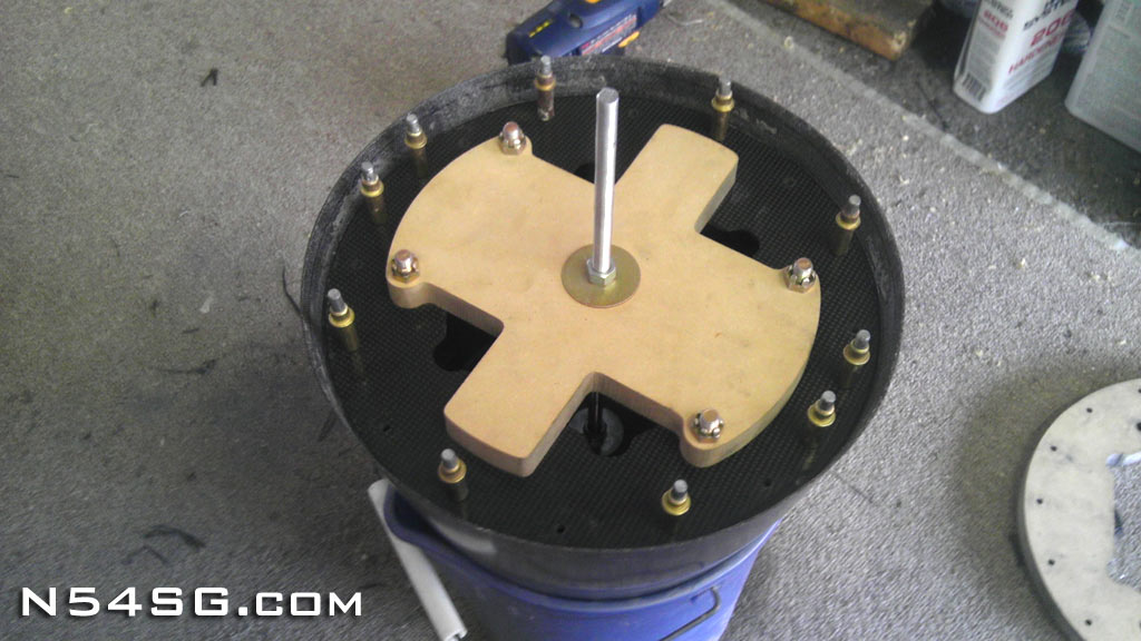
Next I needed some tools to help assemble all these parts, and importantly locate the center. This would guarantee a truly straight part. The forward tool is just a cylinder to replicate the front of the Hartzell piston cover, with a center hole. The rear tool will bolt to the 4 mounting holes and located the center as well. It has a bit of an odd shape so I could reach inside to install the 4 temporary mounting bolts. Both of these parts I had cut out of MDF as well. The idea is to replicate the Hartzell hub inside the spinner dome.


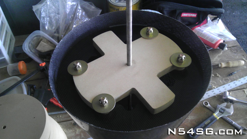
If your still reading, I commend you, and you must really be interested. The next step was to bond the forward bulkhead to the spinner. I mixed up some flox and pressed the bulkhead in to place. Then using my centering blocks I placed them in the spinner assuring the forward bulkhead was centered and straight. (Hard to see in the pics) After it cured, you can see the forward bulkhead bonded in. Worked great!


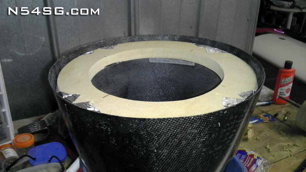
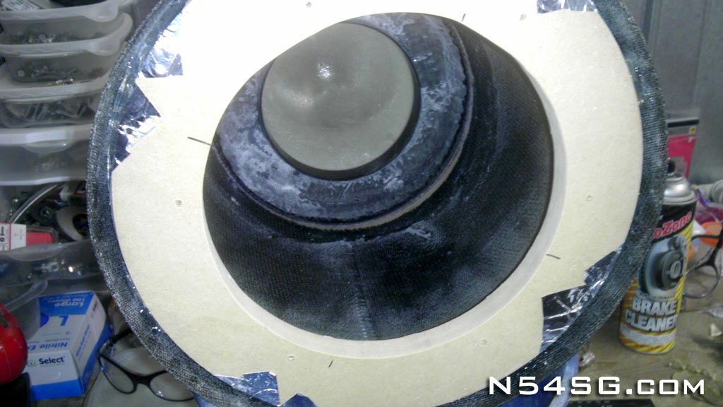
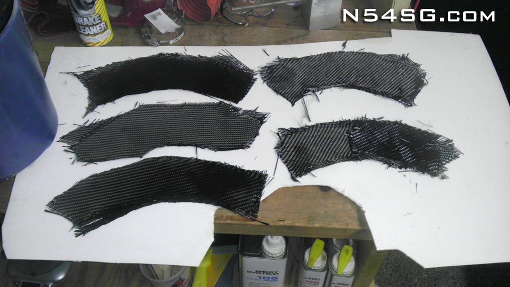
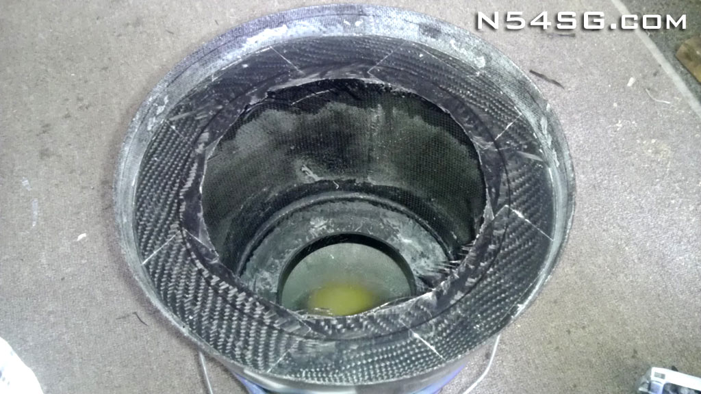
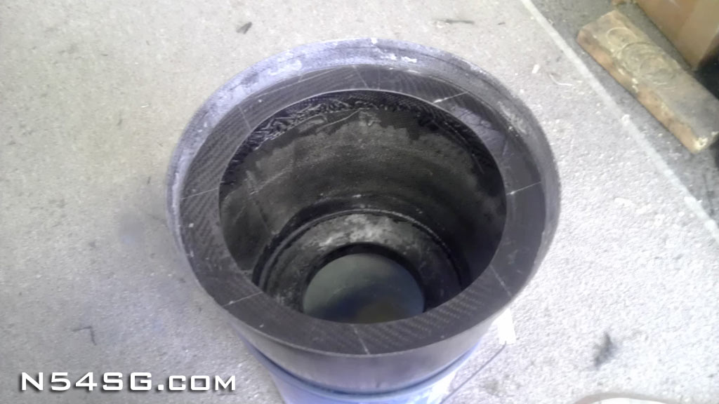
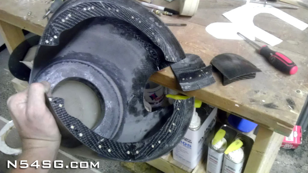
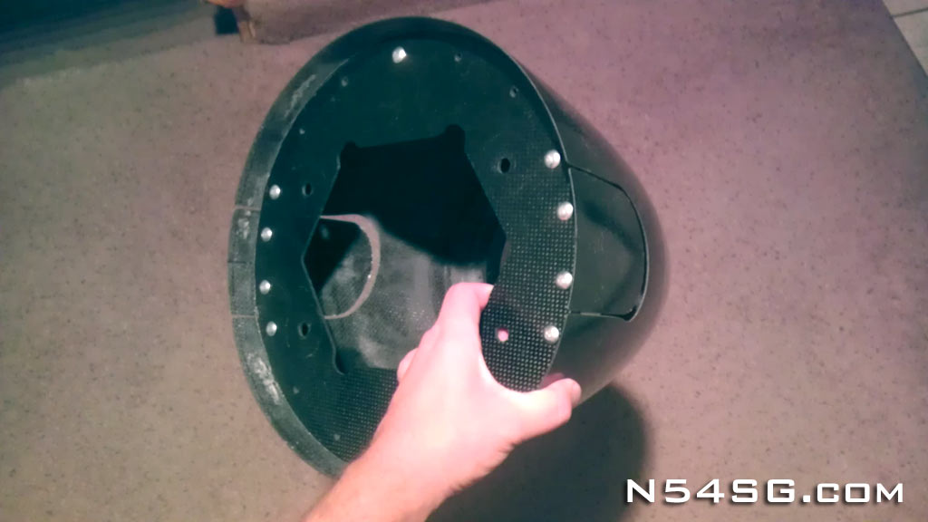
The rear bulkhead install is a bit more tricky. The goal here is to build a flange that is bonded to the spinner dome. Where that flange is located is somewhat tricky. I made a ring out of MDF that I temporarily glued in place, using my centering blocks to assure its alignment. This ring was taped and had mold release applied to the inside. The large center hole would allow me to work inside the spinner. I prepared layers of carbon that were cut in the approximate shape of the inside of the spinner. I applied them one layer at a time, traveling around the spinner as I went. It ended up being about 5 layers thick all the way around. Once it cured I removed my temporary ring and trimmed the flange to about 1.25 inches wide.


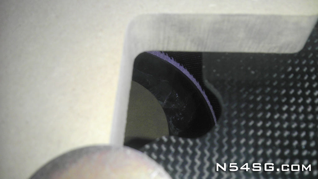
Now using the centering blocks again I could drill all of the mounting holes in the flange and install nut plates. With these holes located, now we have a defined location for the propeller blades. Cutting the holes for the blades is no small task. I made a paper template and just kept trimming till I had enough space, then transferred that shape to the spinner itself. With a single cut I got pretty close. Only small amount of trimming was required after. One cool part about this is the blade spacers have their own flange still attached. So, even the blade spacers will appear screw-less! After I had the propeller back on the airplane I trimmed the blade spacers to fill the gap. Keep in mind, this must be done while the blade is rotated to the low pitch stop. And then give yourself a little extra to be safe.


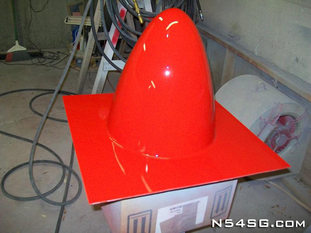
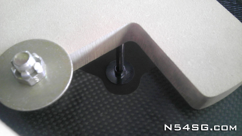
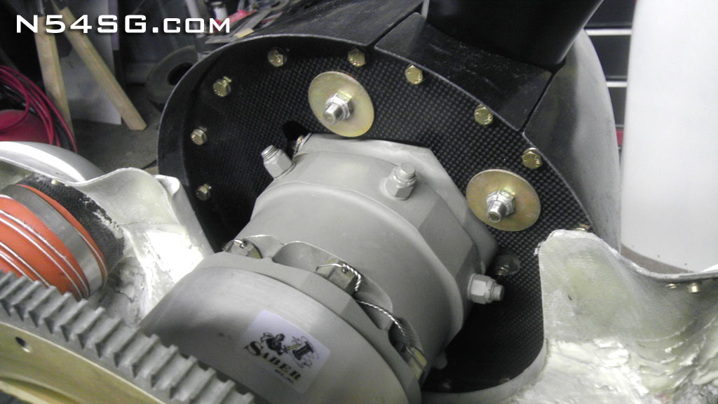
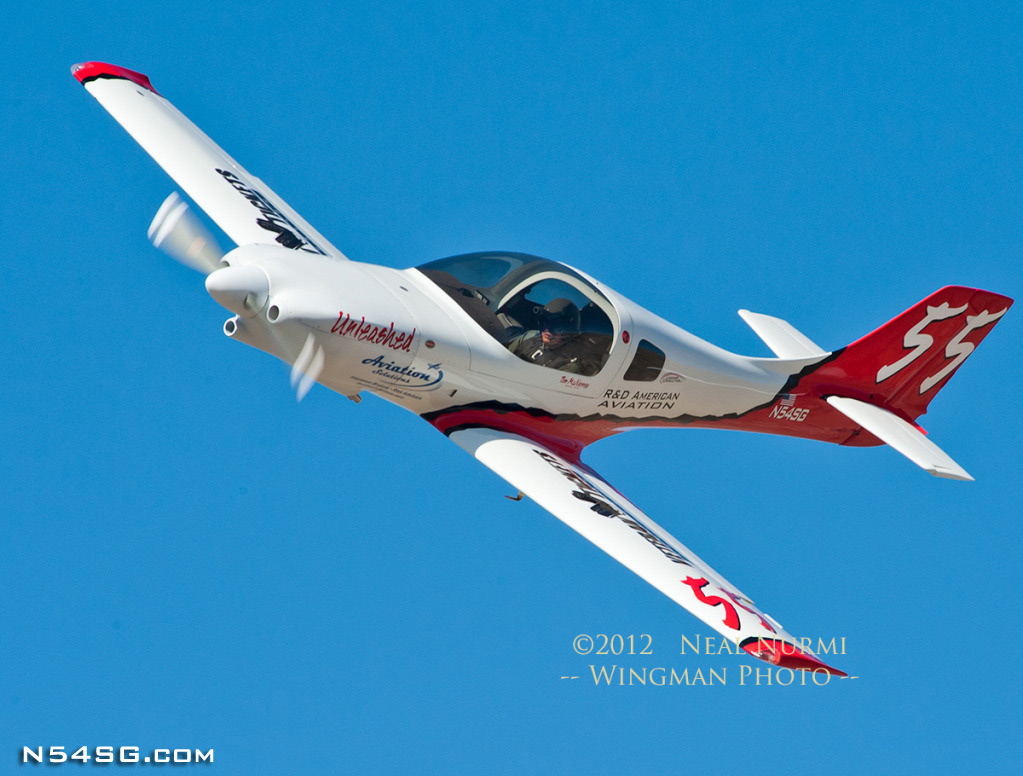
I ended up using AN3-4 bolts rather than screws to attach the spinner. It is just easier to use a socket in that area than a screwdriver. The only catch is you have to remove the upper cowl to get to the bolts from the back. Also, I used big area washers to compress the carbon bulkhead to the propeller hub. I figured it was best to spread out the load some. I finished this project just before Reno last year (2012) and it made through the races at high rpm and still seems to be working great! I like how the hidden screws is a cool little thing few people notice, but when they do they are impressed. With this great tooling I should be able to reproduce this install for anyone interested, just Contact Me for more information. The 3D concept to 268 mph at Reno!


