
This is another of my many projects that happened last year and I am just now getting around to writing a report about it. I suppose part of why I am so slow at covering this might be the fact that I didn’t see much improvement on this one. It is possible that the potential gains cannot be measured with the existing propeller, still my limiting device.
So, on to the modification. This airfoil, a NASA NLF(1)-0215(F) was originally designed as a low speed high lift airfoil for sail planes according to Harry Riblett. Given that the original Lancair 200 was powered by a Continental O-200, that may not be that far off, although the original airfoil designer lists it as a GA airfoil. Now that we are in the 270 mph average lap speed at Reno, I think it is safe to say we are a bit out of the original envelope. So what do we do about it?
Let me preface this article with some facts, I’m not a Dr. Or an aero engineer. But, let’s not let either of those things stop us from practicing experimental aviation or the occasional finger surgery.
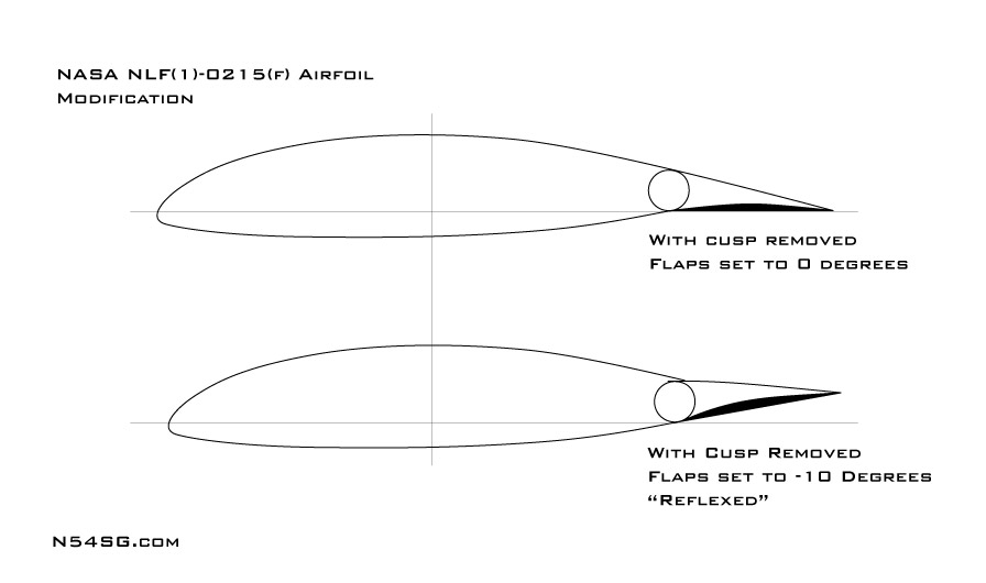
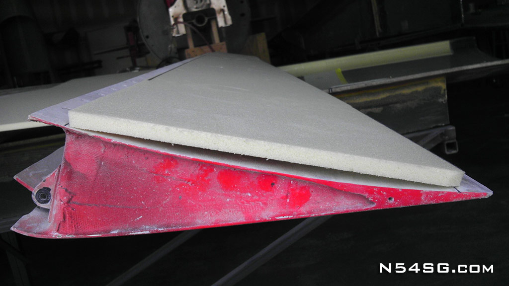
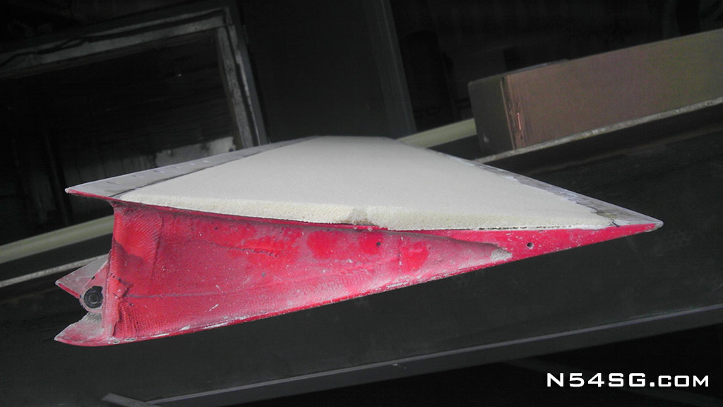
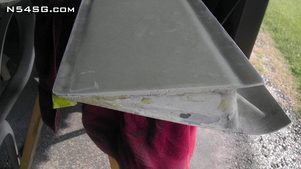
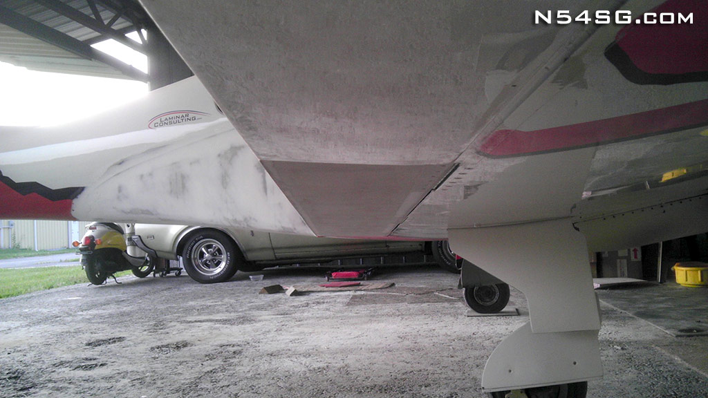
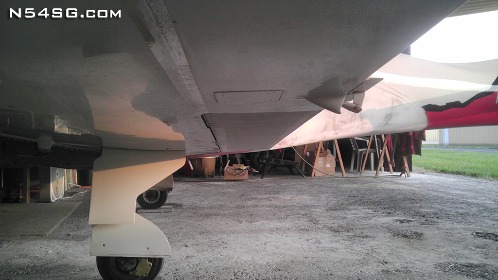
 The first thing most people notice with close inspection is what I call a cusp in the bottom skin of the flap. This concave shape is very noticeable and something that stands out when compared to most GA airfoils. At the same time this wing uses reflexed flaps, that being flaps retracted above the chord line of the wing. This is also something that stands out when compared to most airplanes.
When the flap is in reflex the airplane is the fastest, but I always thought the angle of the skin between the wing and the flap would never allow for any sort of laminar flow. Not that we have laminar flow that far back anyway, but I suspected a rather big low pressure void when the flap was reflexed. Then someone shared this page from Harry Riblett’s book: PDF
That pretty much sealed the deal because I was looking for something to do anyway. By filling the cusp with a straight line from leading edge to trailing edge would be easy enough to do, and maybe get me some more speed. This would also reduce the overall camber of the wing which is rather common on the faster airplanes. Here is a simplified look at the above drawing.

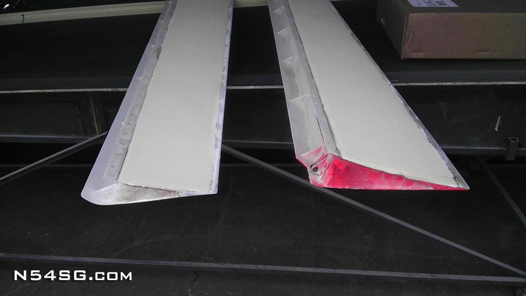
The stock ailerons on a Lancair 320 / 360 already have flat surfaces, so essentially the cusp has already been filled on a good portion of the wing already. That aided in the decision to try it.
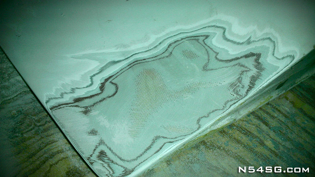 The idea was to sand off the paint in order to get a good bonding surface. I would use last-a-foam bonded into the cusp as a filler that would later be sanded flat. So I started sanding off the paint, and then primer, and then paint, and primer, and so on… I didn’t know if I was ever going to reach fiberglass. Often people ask why my airplane is a few lbs heavier than other 360’s. Well, I’m pretty sure this picture speaks a thousand words in that department.
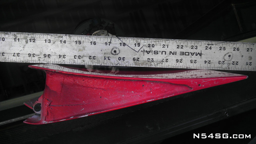
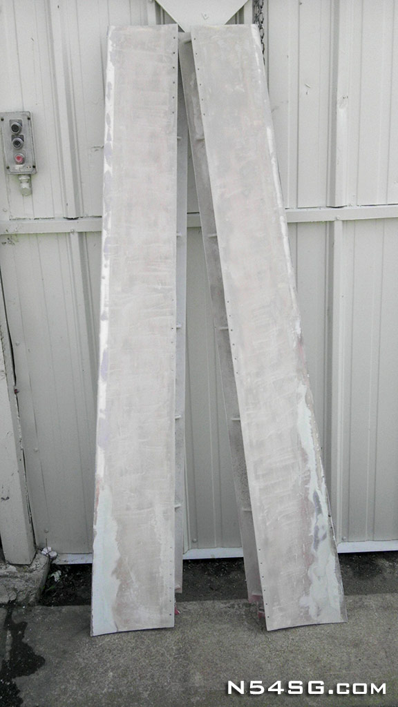
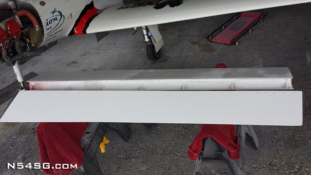
So my DA got switched out for a 60 grit belt sander in an attempt to get this mountain of paint/primer off the flaps as quickly as possible. It still took forever, but the finished product revealed a few things about the airplane. The flaps had been repaired at some point, so who knows the real story.. Here are the finished flaps, albeit much lighter, with the paint removed.
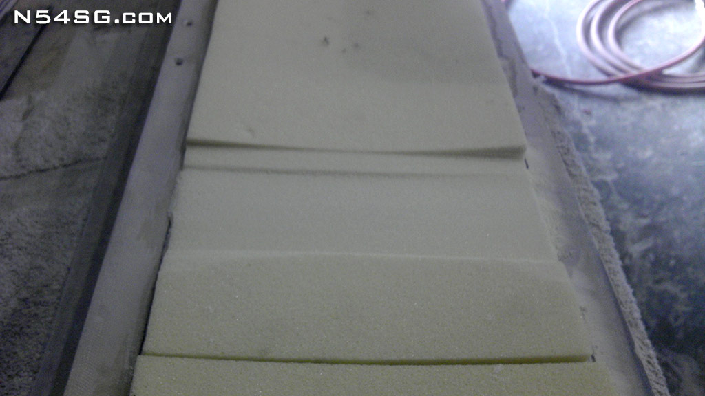
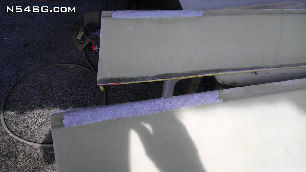
Next I trimmed some 3/8″ foam in the correct size to fill the gap. Last-a-foam does have a certain amount of flexibility to it so this would allow me to bond it to the curved surface of the original skin. I mixed up a rather wet batch of micro and used that as a glue to bond the foam to the flap skin with some help of some extra weight loaded on the foam.
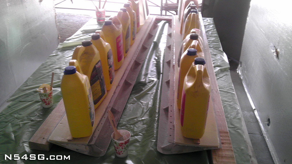
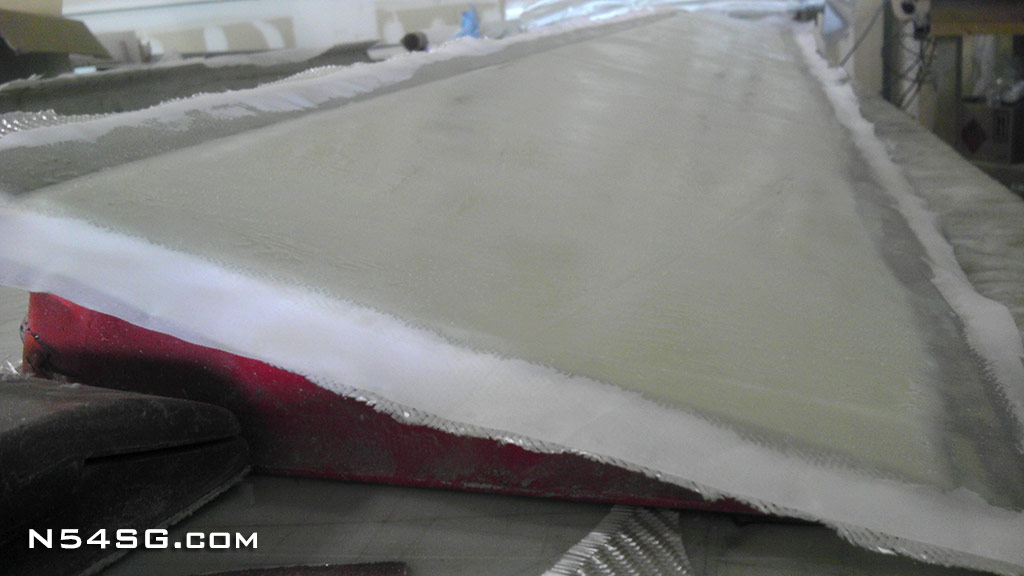
With this set cured I can simply take a flat sanding block and level the foam between the leading and trailing edges of the old skin. I left about one inch of bonding area that I will use to attach the new fiberglass. This would ensure a good surface to bond and prevent any future delamination.
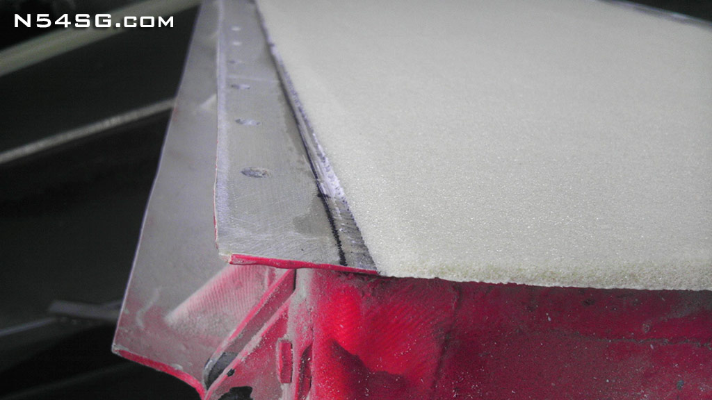
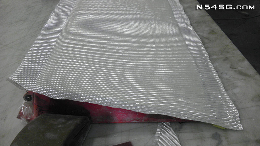
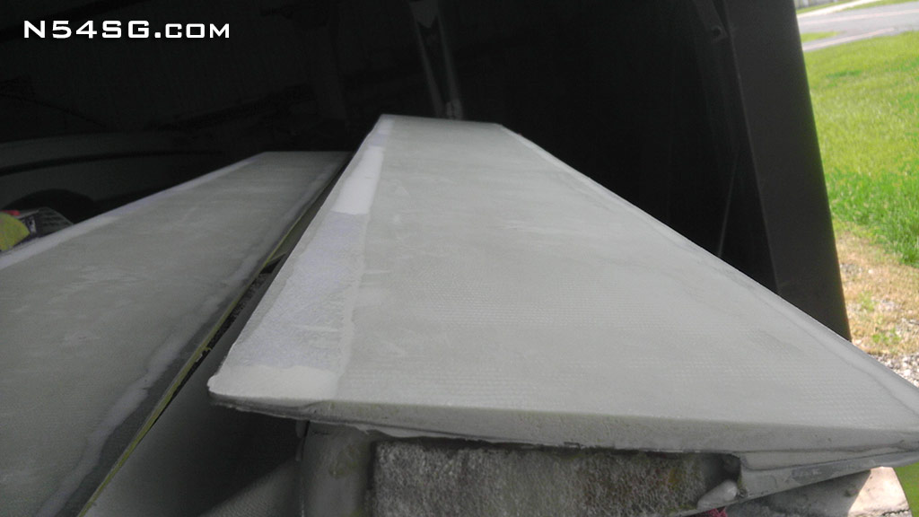
Now that the foam portion is complete, I covered the foam with 2 layers of fiberglass and peel ply for a nice finish.
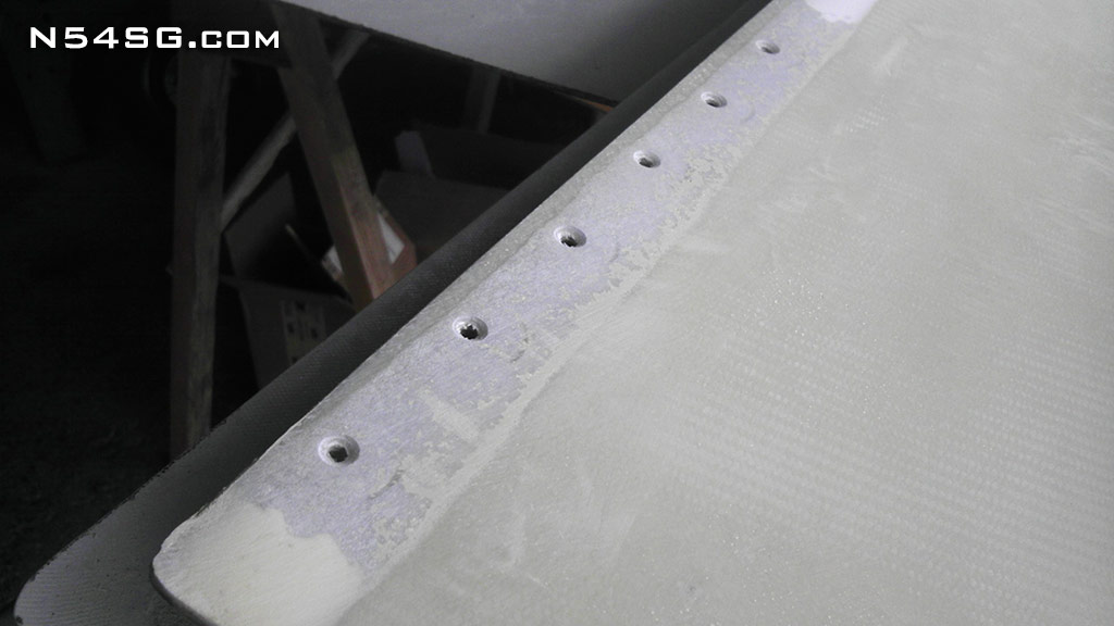
The flap mounts to the wing with 3 sections of MS2000-1 hinge. These are attached with countersunk screws. I wanted to be sure to support the head of the screw so I mixed up some flox for the areas around the screw holes. This would prevent any problems in with the screws in the future. Next I filled the beveled edge with micro to complete the smooth surface and counter sunk the mounting holes.
At this point it was worth doing a trial fit to make sure nothing was out of line. Once installed I was rather surprised how well it looked when compared to the ailerons. All it needed now was to remove and shoot some primer on it till I get around to a real paint job. Yeah, like that will ever happen!
So was it worth it? Eh.. I can’t say for sure exactly what sort of speed gain I may have gotten from this modification. Again I have ran into the same problem where the propeller just won’t pull anymore. What I am doing though is increasing the speed at the low end of the useable rpm. Now, at 9,500 feet for example, the lowest RPM I can govern to is about 2,450 rpm. That is where the blade hits the pitch stop. Generally this is between 255-260 mph true airspeed. So yes I have made it faster in cruise flight, I just don’t have a prop to give me the gains on the top end.
An interesting side effect is how the wing performs under G load. The airplane feels like it bleeds less energy. This was confirmed by Dave Morss while racing at Reno last year. He mentioned that I can pull G’s around pylon 4 and I would pull away from him in the corner. The year before that and I would fall way behind. So it is very possible the lift coefficient is better for a greater overall wing loading, if I understand that correctly, therefore less induced drag.