
I finished this project about a year ago, just prior to going to Pylon Racing Seminar to get race qualified. It has taken me this long to get motivated enough to revisit all of these images and describe the process. That should be an indication of the distaste I had for this project. Lots and lots of work.
For starters, many other items had to be addressed before I could build the cowling. All of the other engine related variables had to be determined as each item would end up defining the shape of the cowling. All of which I have previously written about.
With those tasks complete I could then start to build the cowling. The cowling that came with the airplane was terrible. It had been hacked, molded, trimmed, hacked some more, sort of painted and flown for 250 hours. That cowling started as a beautiful cowl made by Chris Zavatson, when the airplane had a parallel valve engine. His cowling is a tighter fit than a stock Lancair cowling. So, when the big angle valve XP-400 engine was installed, it just wasn’t going to work. I had always planned to build a new cowling but needed to address so many other things (listed above) before that could happen.


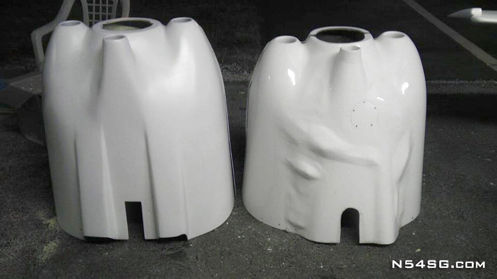
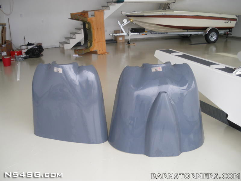
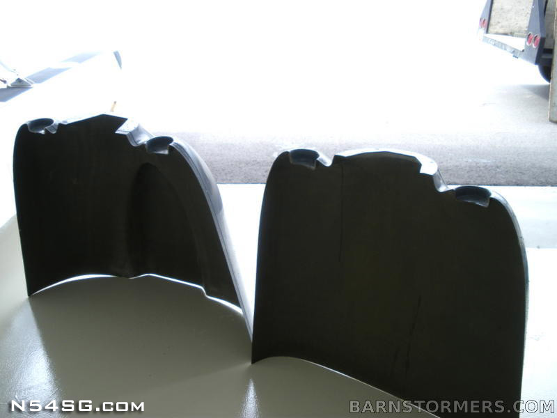
Where to start.. I found a set of original short Lancair 360 cowls up in Canada. Being short didn’t bother me really as I would have to extend either version due to the prop extension. Also, this would allow me to shape a more pointy cowl. If not for speed, at least it would look cool. Most Lancair people don’t notice how different it is until it is parked next to a stock cowl. Starting with a set of stock cowl gave me a good head start. The firewall shape was defined and it gave me a good starting point to build out and forward.
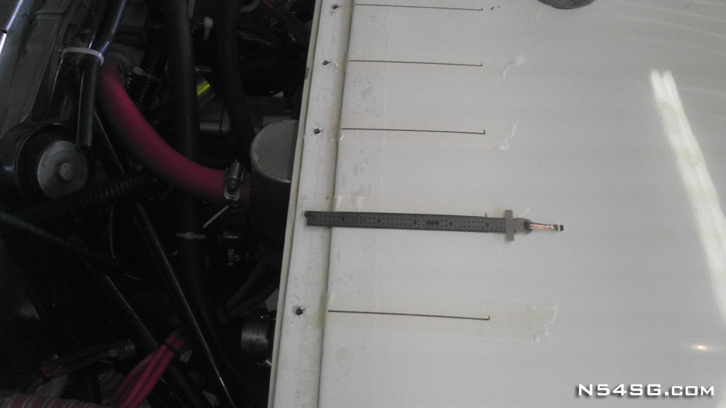
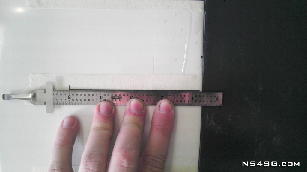
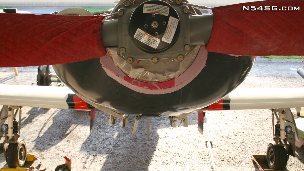
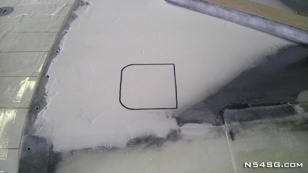
First I located all of the cowling fasteners by drawing a 5 inch line to the center of the nut plate. Then with the cowling in place I would know where to drill. I aligned the cowling so the flange for the top/bottom cowl would be level with the airframe. It just looks better. Also I knew I would have to extend the bottom of the cowl anyway to clear the bulk of the engine, so having a higher than normal alignment wouldn’t be a bad thing. It allowed for more cylinder head clearance also.


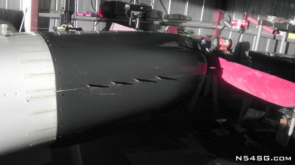
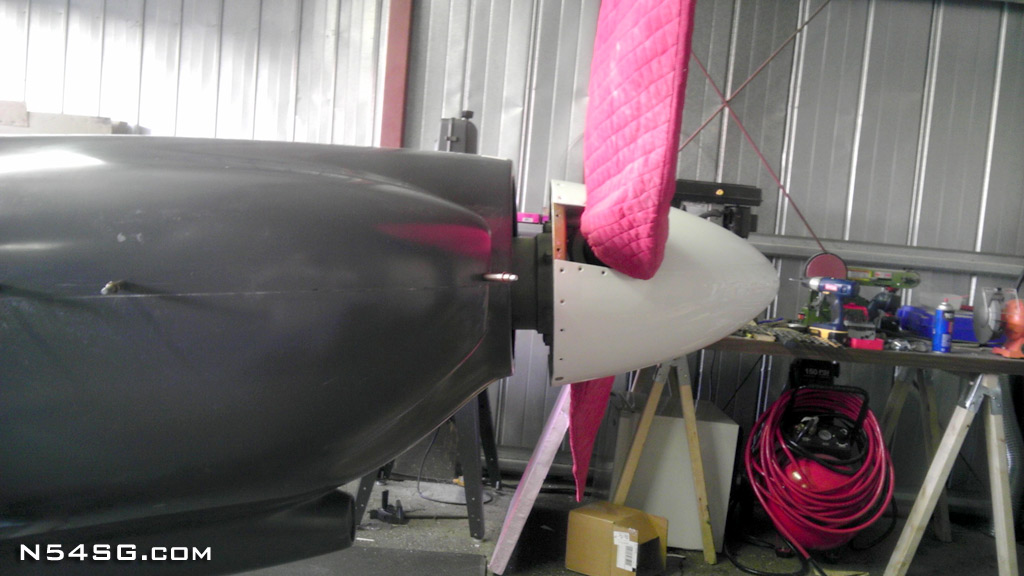
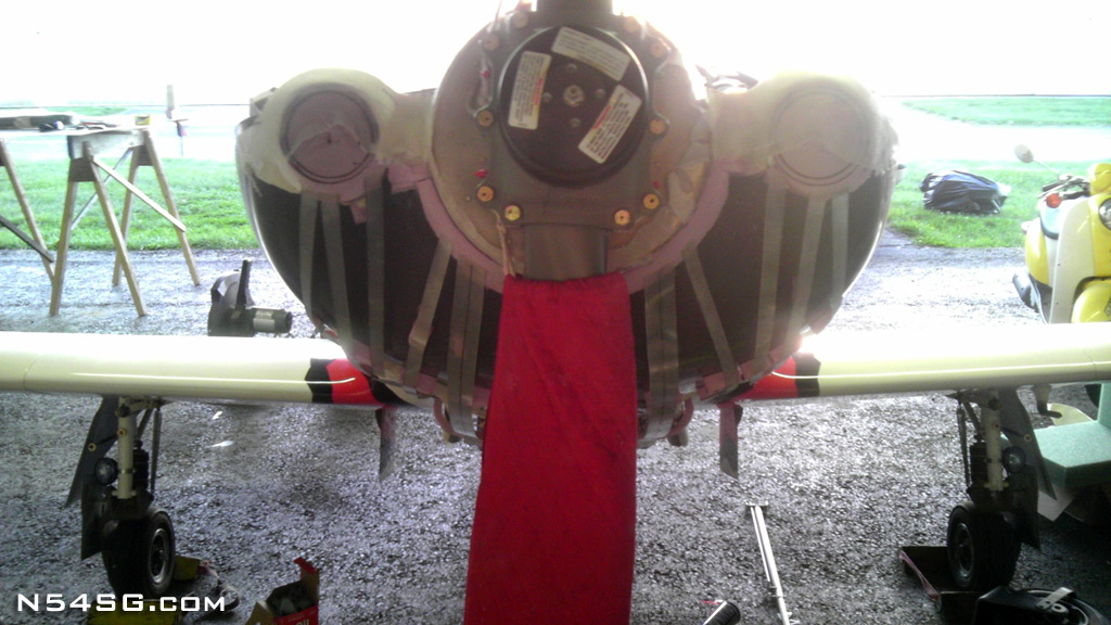
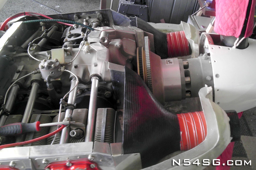
The next few pictures show how far off the spinner is. Not only in length due to the prop extension, but also in yaw due to my engine angle change. Those are subjects on their own, so be sure to read about them. No need to re-hash it here.


I started with the top cowling. I extended the cowl to meet the spinner and eliminated the yaw that is molded in to the cowling shape. It took about 12 inches to blend that shape back in to the cowl, but it worked. I also started adding some height to the cylinder head area. The angle valve heads are taller and wider than a stock parallel valve engine. (what the cowls were made to fit) I wanted to end up with plenty of room for the baffles and plenum, but wanted to blend that shape as best as I could. That is part of what makes this airplane cool, it is totally different, but only to the trained eye.


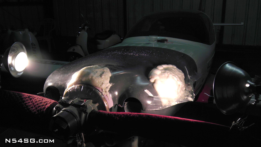
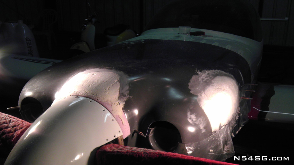
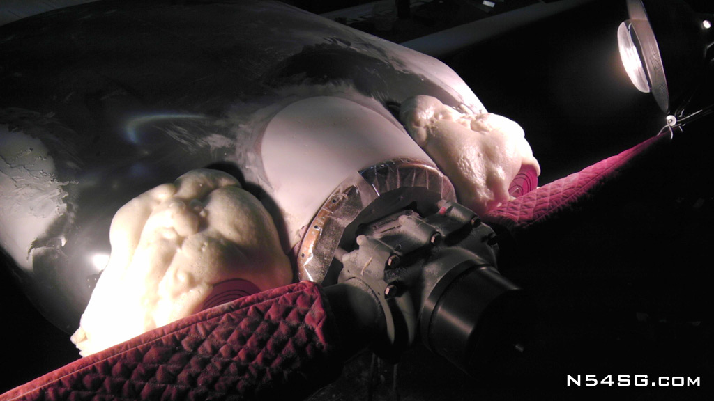
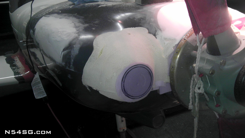
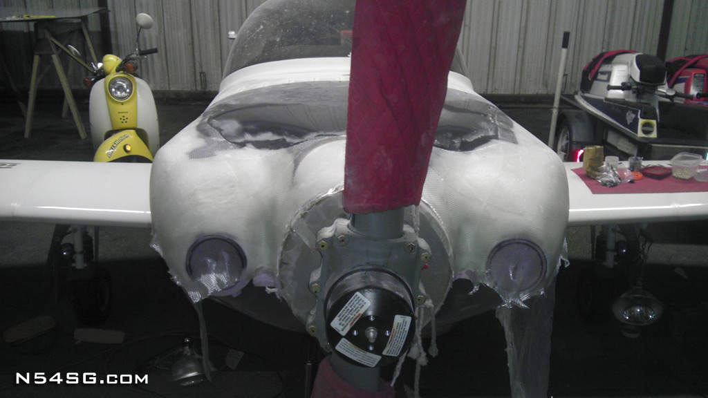
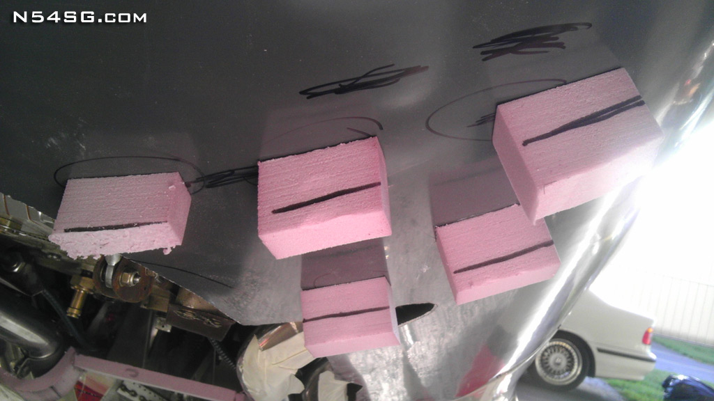
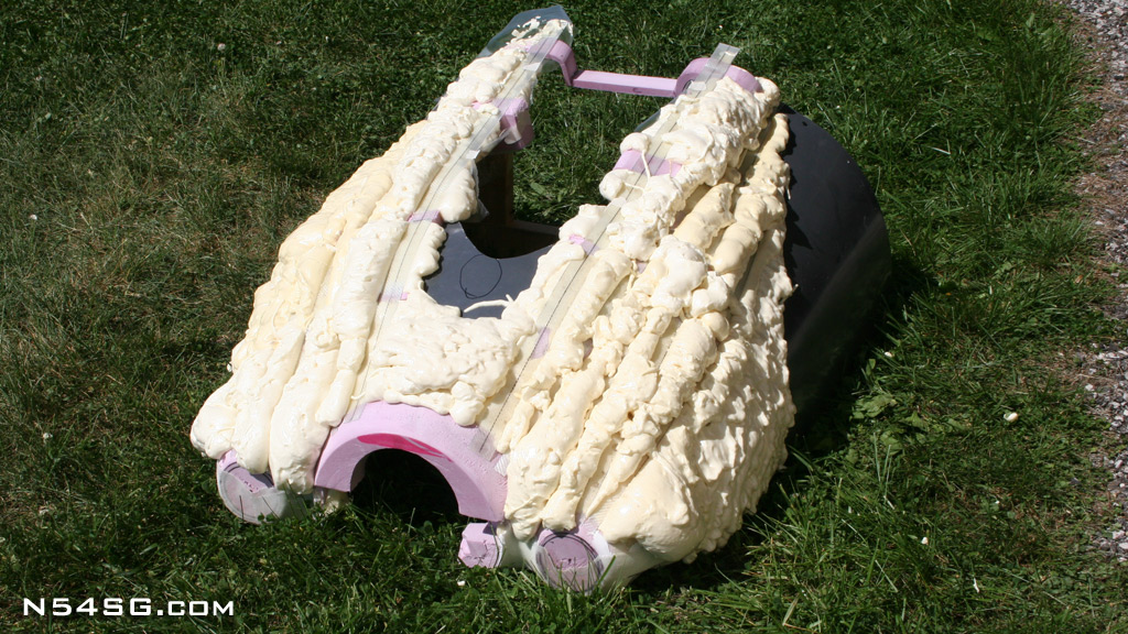
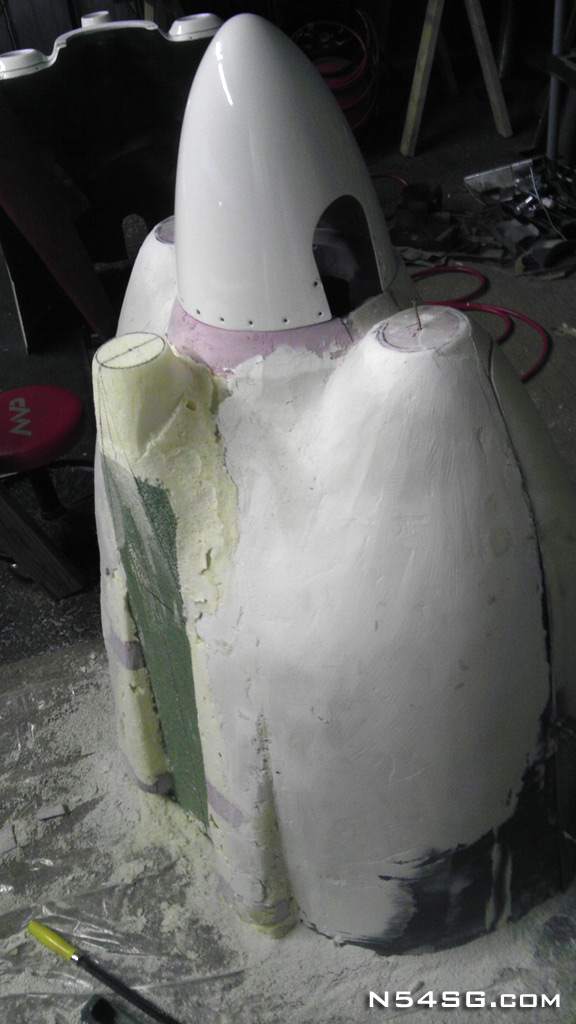
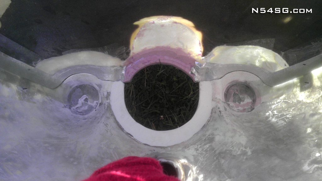
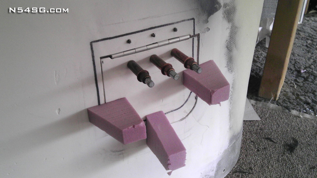
Next I needed to locate the cooling air inlets in space. I hot glued some pink foam in place with circles that would represent the air inlets. I reduced the distance of the inlet to the spinner by half an inch compared to my old cowling. The prop extension gave me the room to blend the shape in and it would also give the nose a more pointy look. Once the inlets were located I covered the area in 2 part expandable foam. This was going in to winter at this point and I am working out of my T-hanger. Needless to say, it took some heat lamps for the foam to really kick off. When cured I sanded the foam to a ballpark shape. But, the foam is pretty soft stuff and for whatever reason it kept shrinking. At this point I wanted to secure the shape so I covered it all with a layer of micro and 1 bid of 7725 fiberglass to protect it during the rest of the project.


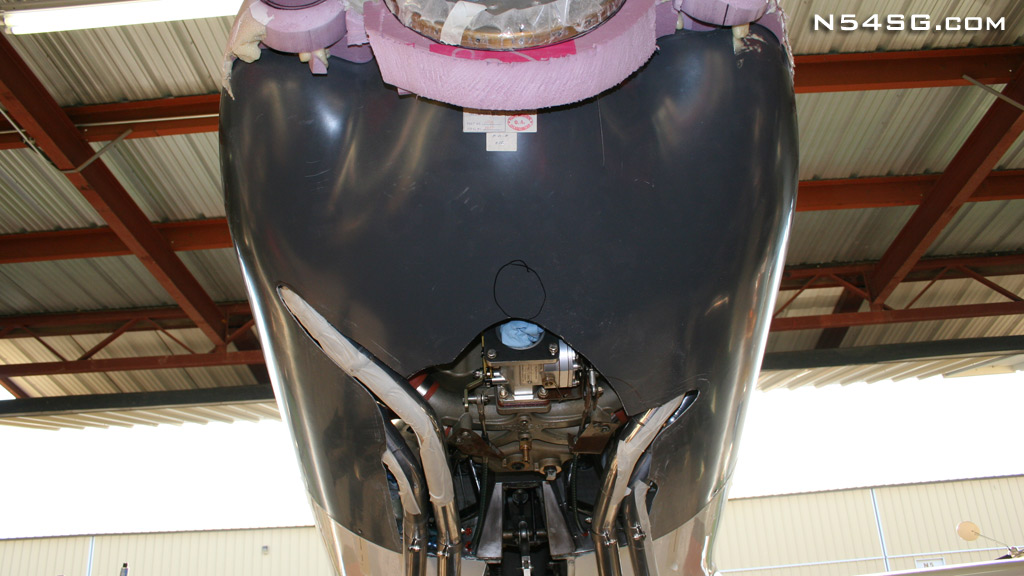
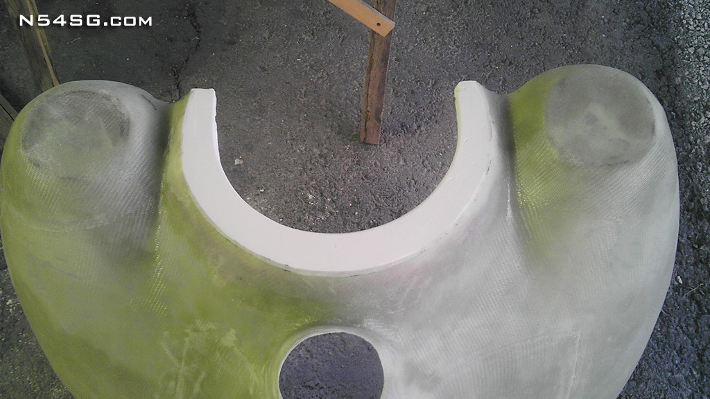
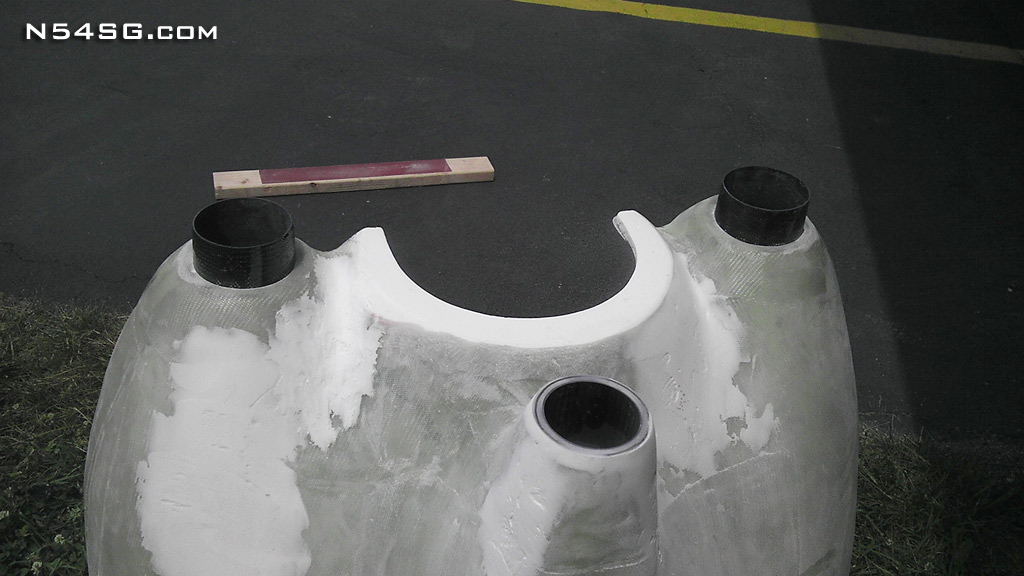
I wanted to maintain the same design as my original cowling in regards to the inlets. The lower cowling would have the entire air inlet, this way it could be a tube that would seal to the diffusers/plenum. Most cowlings have the air inlets split down the middle and it makes it much more difficult to create a positive seal. I cut the inlets out of the top cowling and left them bonded to the lower cowling. With my new exhaust this will be a very tight cowling. But, it still required cutting out the majority of the lower cowl due to this engine being wider/taller.


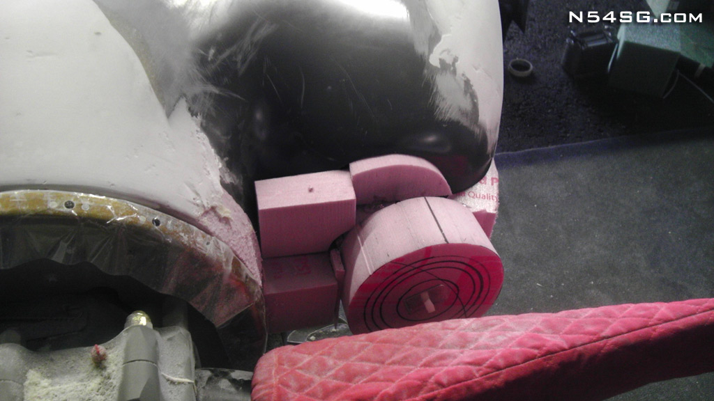
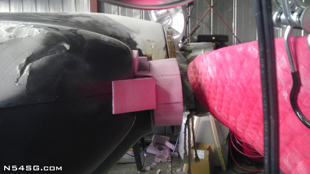
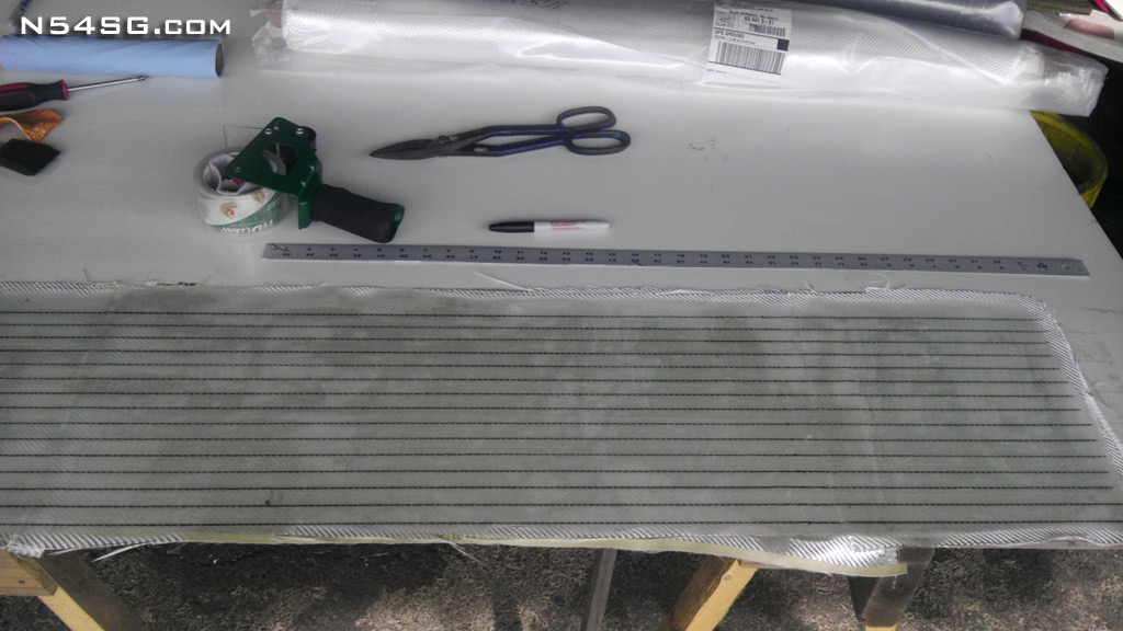
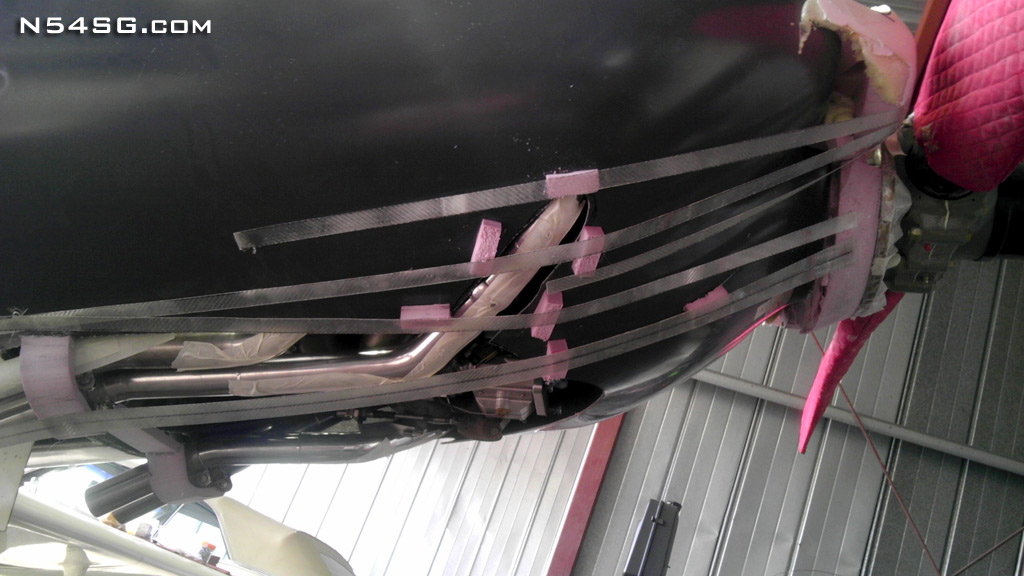
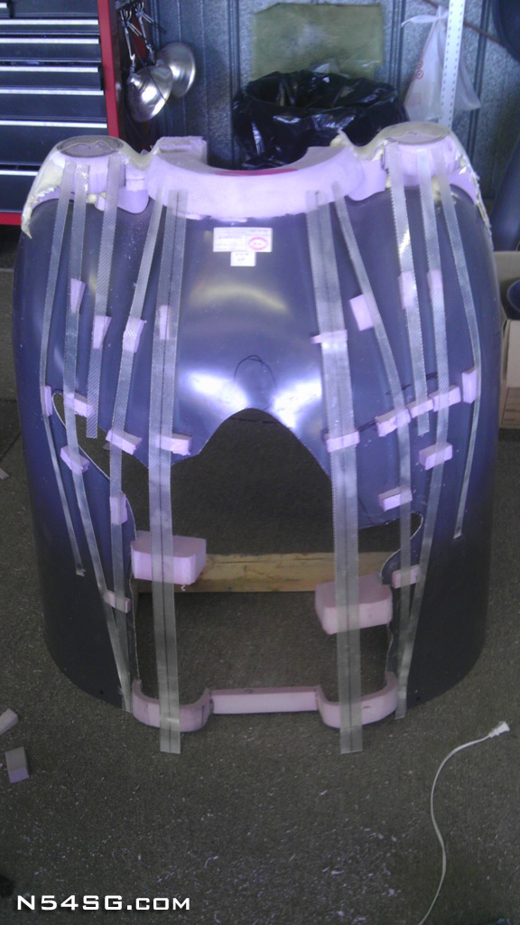
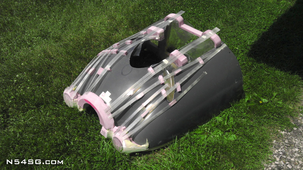
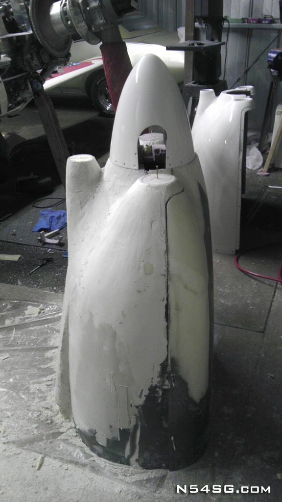
It took me some time to figure out a way to design the cowling shape. I needed to be able to visualize the shape on the airplane, but then reproduce that shape with the cowling off the airplane. So, I pre-cured 2 bid fiberglass and cut them in to long strips. They were flexible yet allowed for some creative curves. I glued some pink foam in key places along the cowling. Mainly the few known points that had to clear the exhaust and allow for engine movement and heat. Then I glued my strips in place to define the cowling shape. This sounds easier then it was. It took a lot of time to decide what shape looks and will perform the best.


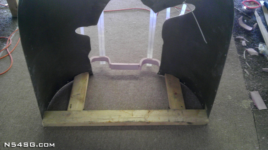
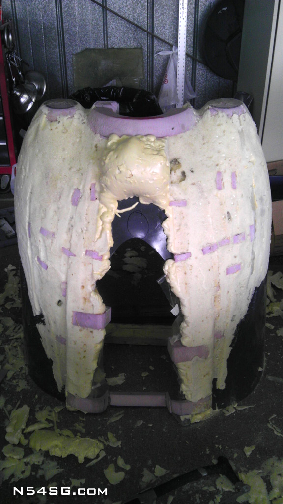
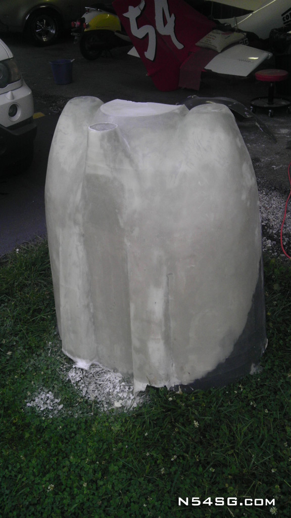
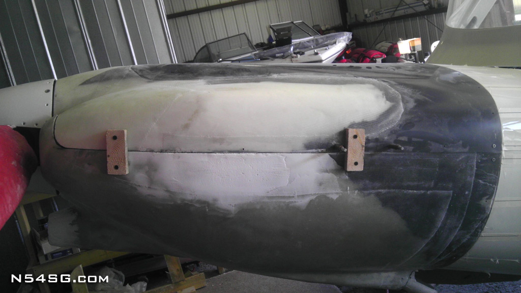
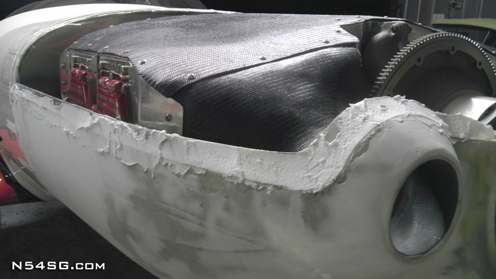
As I said before, this fabrication would have to take place off the airplane. So with the cowling removed I screwed a 2×4 template to the firewall flange of the cowling. This would maintain the correct firewall shape during the process. Next I covered the bottom cowl with expandable foam and allowed it to expand around my template strips. When cured I cut the foam down to my template lines and had a basic shape.


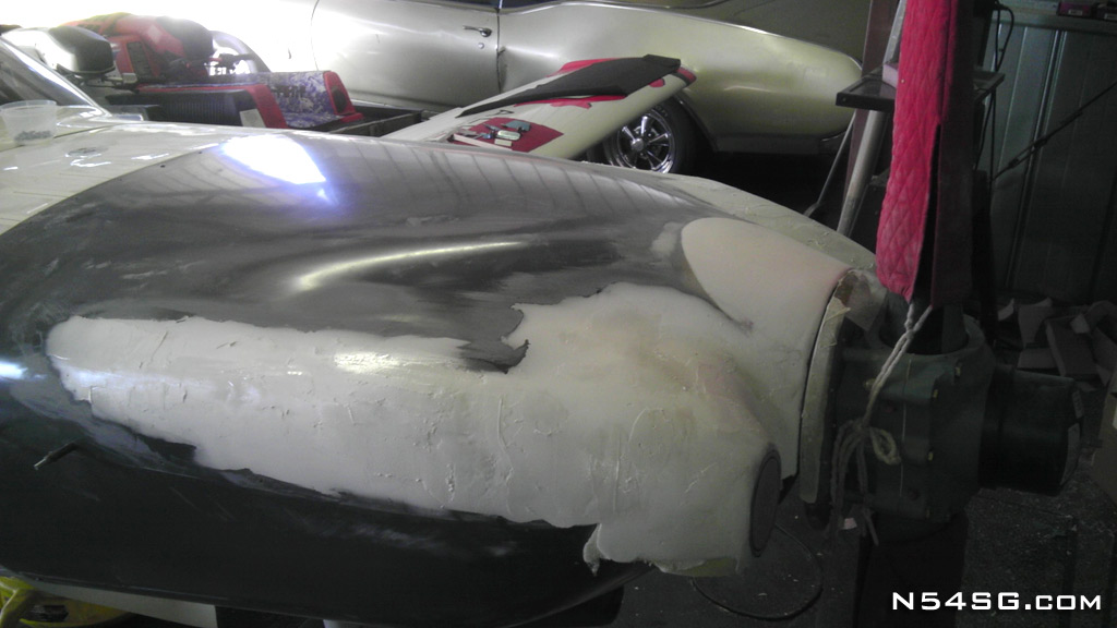
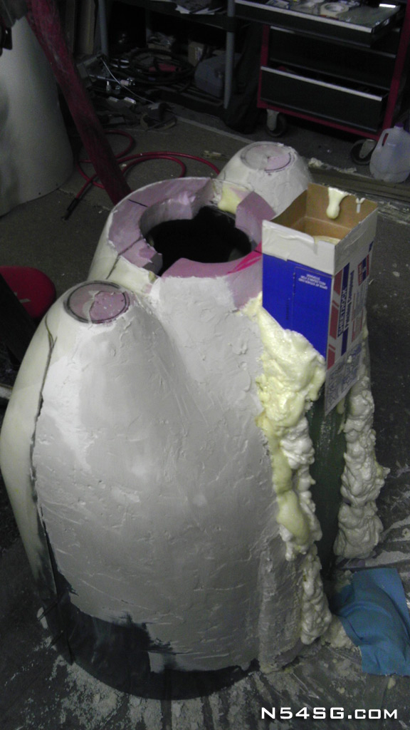
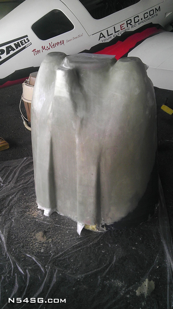
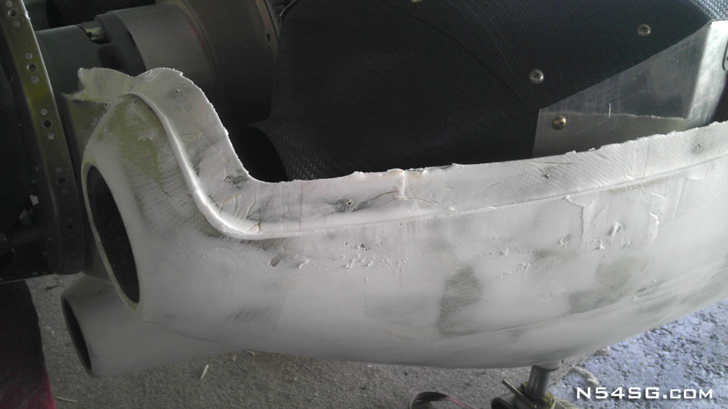
The next problem was what I had experienced with expandable foam before. It shrinks over time. The next day it had shrunk some and I lost the contour I had worked so hard to shape. I went looking for a quick, cheap and simple way to cover this foam and fine tune the design. Micro was out as it would take a huge amount and much too hard to sand/shape. I thought about some form of modeling clay, but it also didn’t seem very plausible. I ended up using quick setting drywall compound. The same stuff used to patch holes in drywall. It was cheap and I could quickly mix up a batch, slap it on, and be shaping it within an hour or so. It took many applications and a lot of artsy work to reveal the cowling shape.


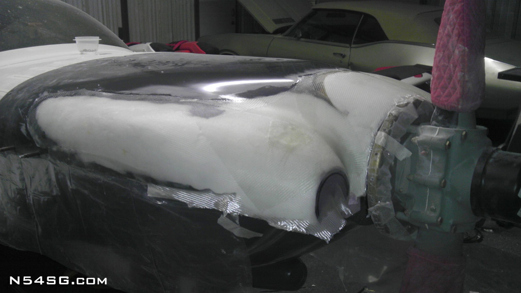
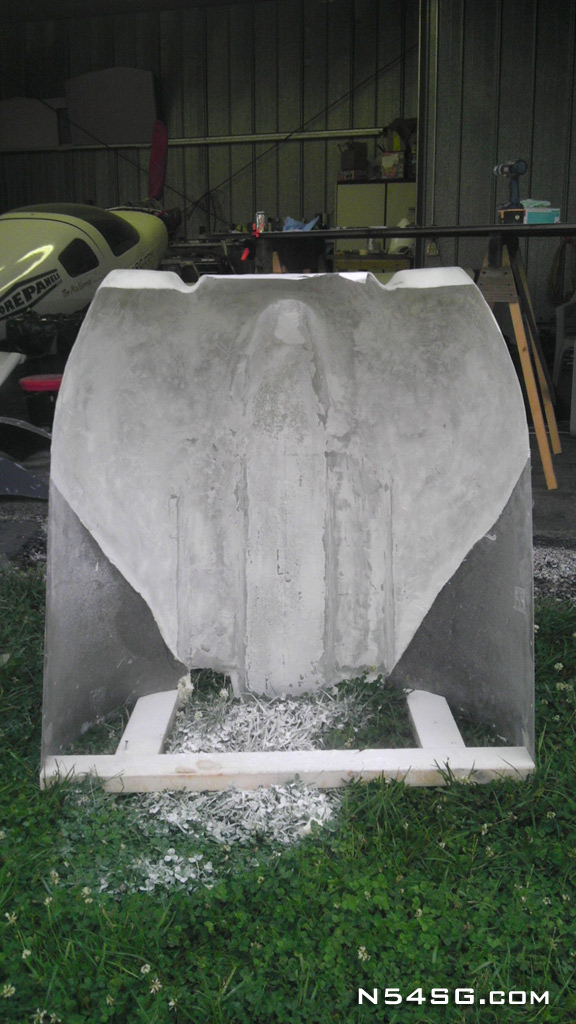
So with this shape defined I covered it with 4 bid fiberglass. Once cured I returned to the inside of the cowling and removed all of the foam/drywall compound etc, leaving the firewall flange from the original cowling. I also added a micro ring around the propeller hole adding some strength.


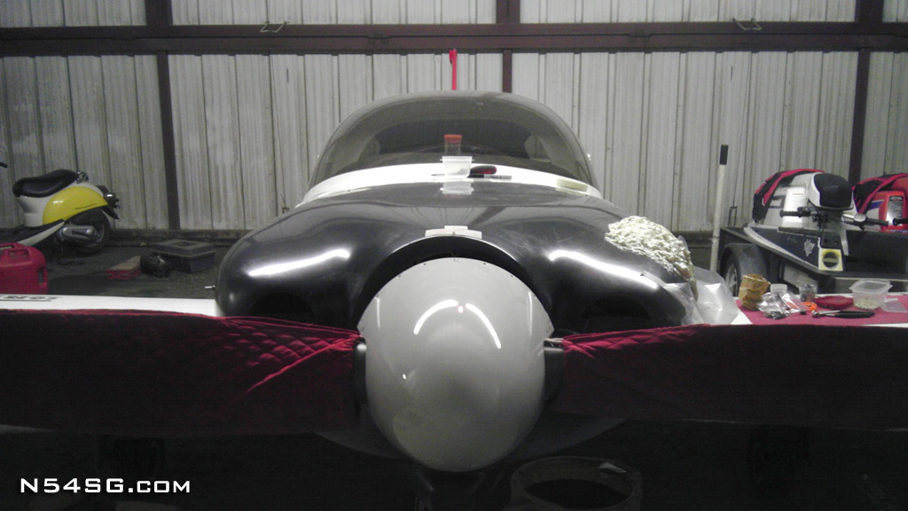
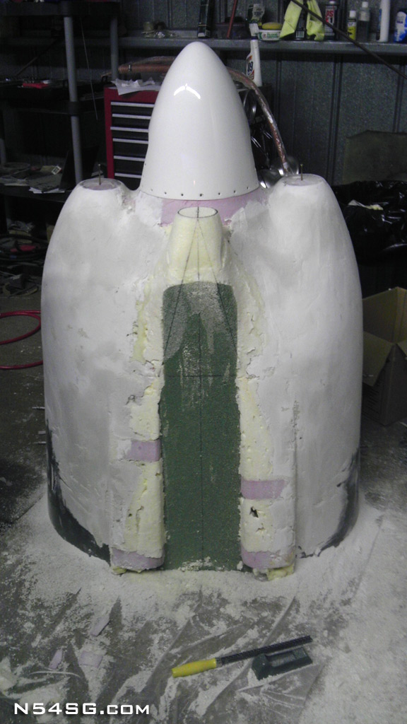
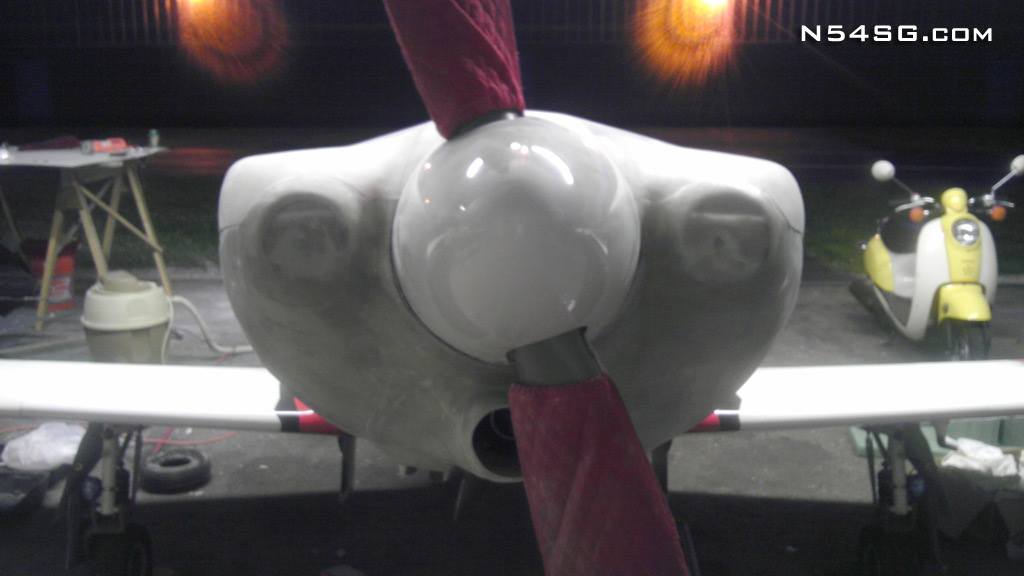
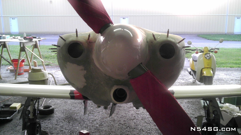
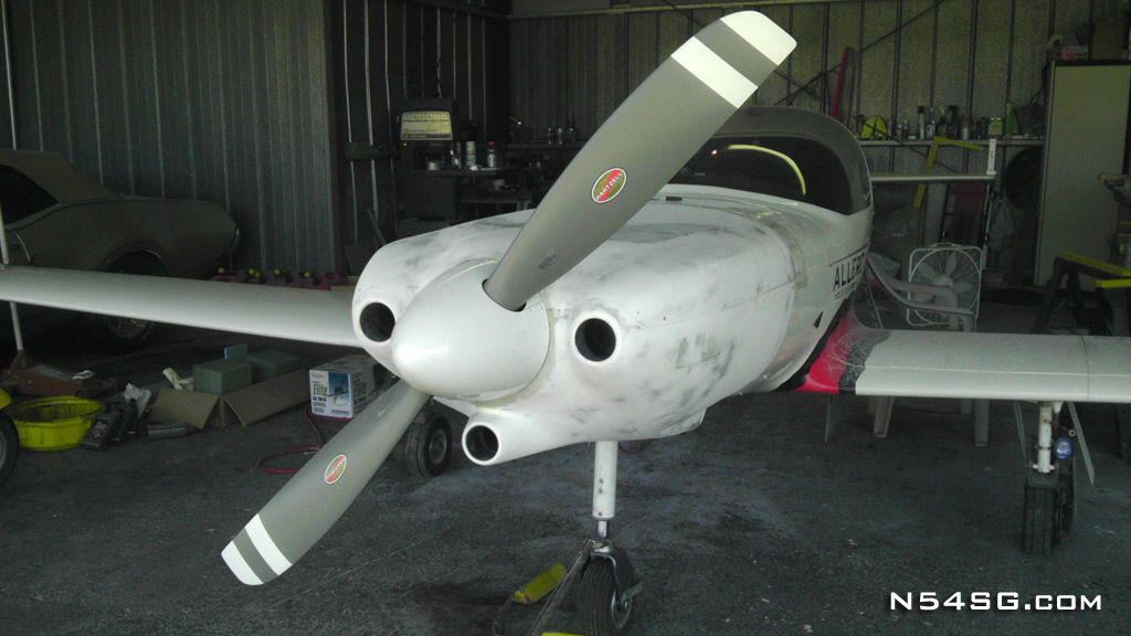
Now to see if what I sculpted standing vertical would look ok on the airplane! Not bad for the first try. I had to make some small changes to keep things symmetrical, but over all I was pretty close. As you can see from the front of the airplane, the bottom of the engine inlet is almost a straight line to the leading edge of the nose gear door. (The nose gear is removed in these pictures) With the previous cowling, that trailing edge was 8 inches below firewall at that point. Imagine that going 250+ mph.. It may not seem like that is a big deal, but for any 320/360 owners, look down your cowling and imagine being able to see top edge of your gear door!


At this point I still had to add a flange to the bottom cowling so the top and bottom cowls could be connected. I screwed some temporary wood blocks to the outside of the cowling, while it was in place on the airplane. Then I could remove the cowling and reassemble it with these wood blocks, thus reproducing the shape as it is on the airplane. With the top cowl taped and mold release waxed I added the flange to the lower cowling. Once cured I could drill and cleco the cowling together.


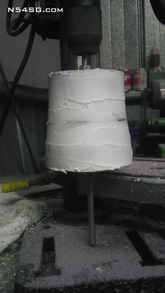
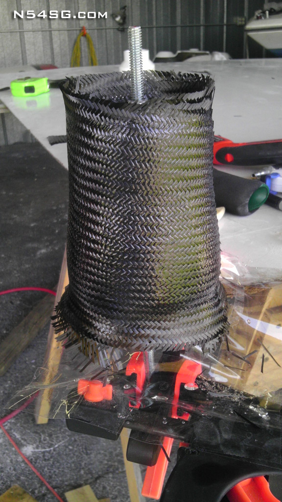
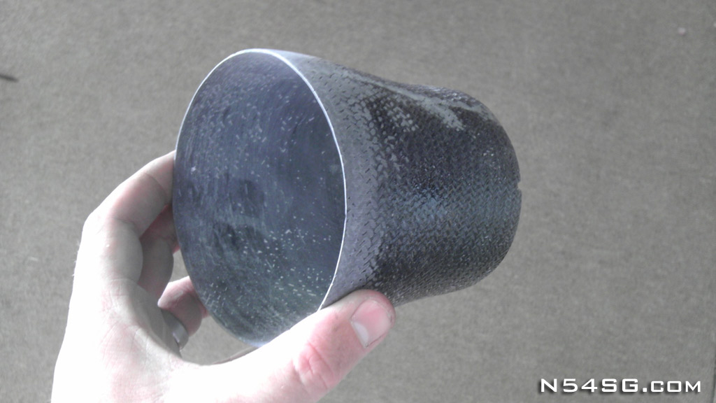
I was unable to complete my plenum and diffusers until I had located the air inlets on the cowling. I wanted to have this all done at the same time that way I was sure I would have perfect alignment of the air inlets. So, I needed some air inlets. I used the same design principle as was used on my old cowling. The previous diameter inlet had worked ok, but I was sure I was going to better the overall cooling efficiency anyway, so I stuck with the 3.5″ diameter inlets. The trick here is to expand the inlet as soon as possible. In this case, it expands from 3.5″ to 4″ diameter within the first 2″ of depth. So as the air enters the inlet it immediately starts to expand, slowing, and increasing pressure. Then it passes through the 4″ sceet tube union to the diffusers where it expands to the engine plenum. The engine inlet remained 3″ diameter as the previous cowling had. This worked well. The difference here is I used a bit bigger radius around the lip of the inlet. All 3 inlets extend beyond the spinner edge about 1″ if I remember correctly. This helps keep them in clean, undisturbed air while still clearing the trailing edge of the propeller blade, at course pitch.


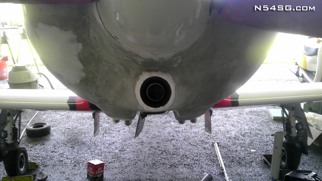
Well, have to check the oil… I chickened out and moved it at the last minute. Glad I did as it is perfect now for adding oil without a funnel.


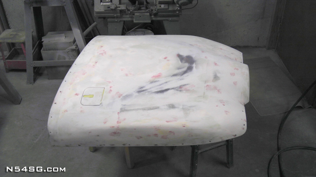
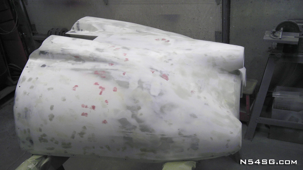
I wanted a very clean cowling line so I did a dry micro press on the lower cowl flange. With the top cowl release taped and waxed I pressed it in place, waxed the cleco’s and inserted them insuring a snug fit. The end result is a perfect cowling edge.


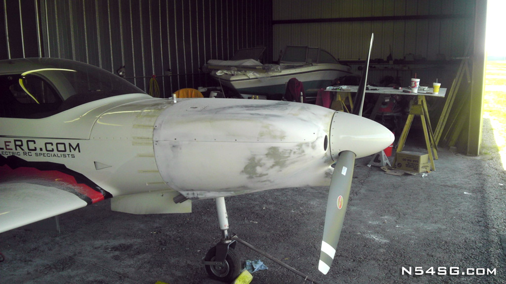
Bodywork, lots and lots of bodywork. This had to be done on the airplane so you could get the best perspective. The top cowl required a lot of filler between the firewall and about the middle of the cowl. The original mold from Lancair must have sagged some and there was a rather large dip on the cowl that was very noticeable from the side view. I was in a time crunch at this point so we quickly filled all of the pin holes we could find, (still missed plenty) shot some primer on it and went to Reno for PRS.


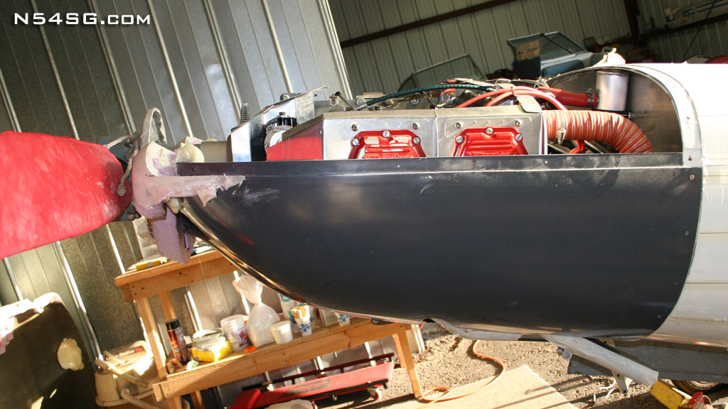
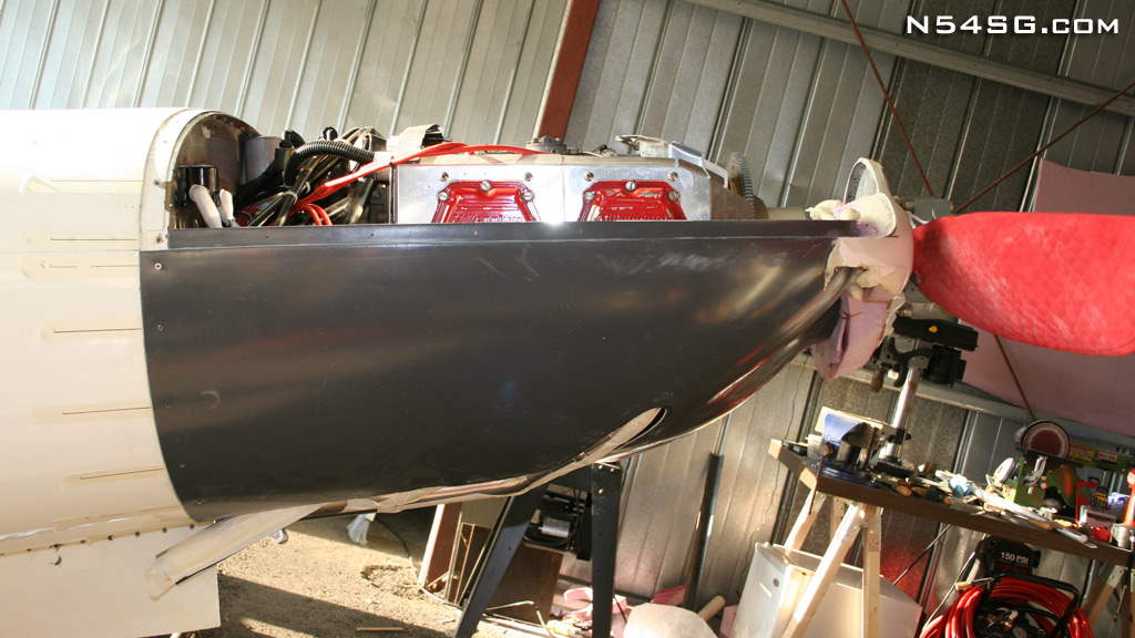
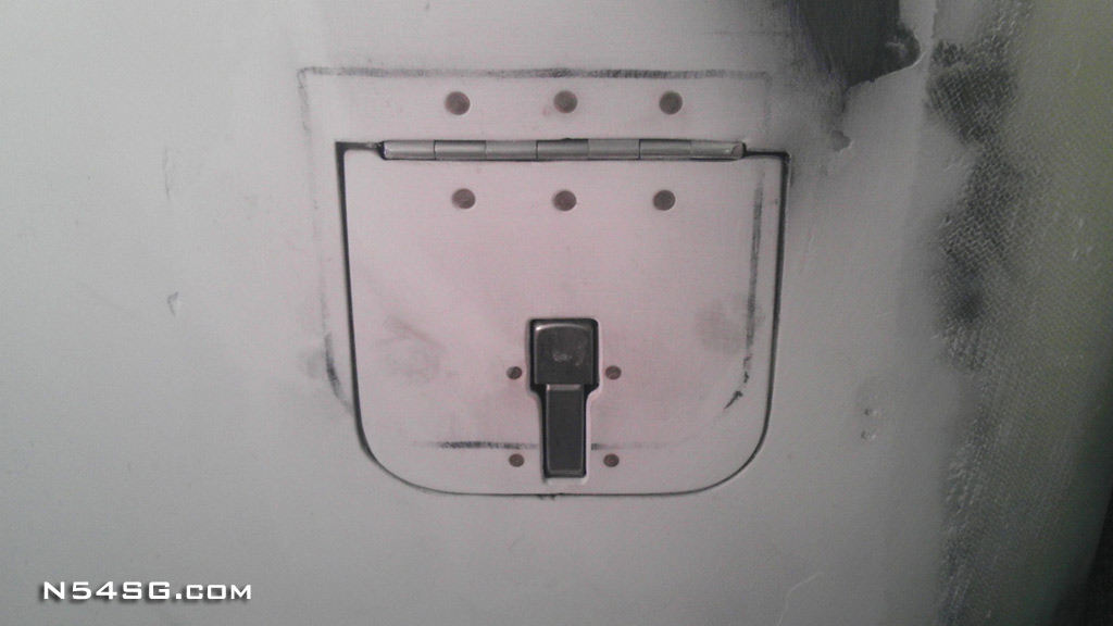
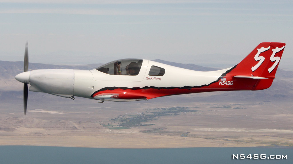
As you can see in the photo below, it is a landmark improvement compared to the old cowling. Switching from the 4 into 1 header to the 4 individual pipes was absolutely worth it, even if there was a horsepower loss. The trailing edge of the cowling has 1/3 of the cooling air exit area compared to the old cowling, and it cools better! The nose gear cut out is square as I plan on including a gear door for this area, closing down more exit area. Also you can see the difference in length due to the propeller extension. My opinion is all airplanes should have as long as a propeller hub as possible, it just makes everything better!

