
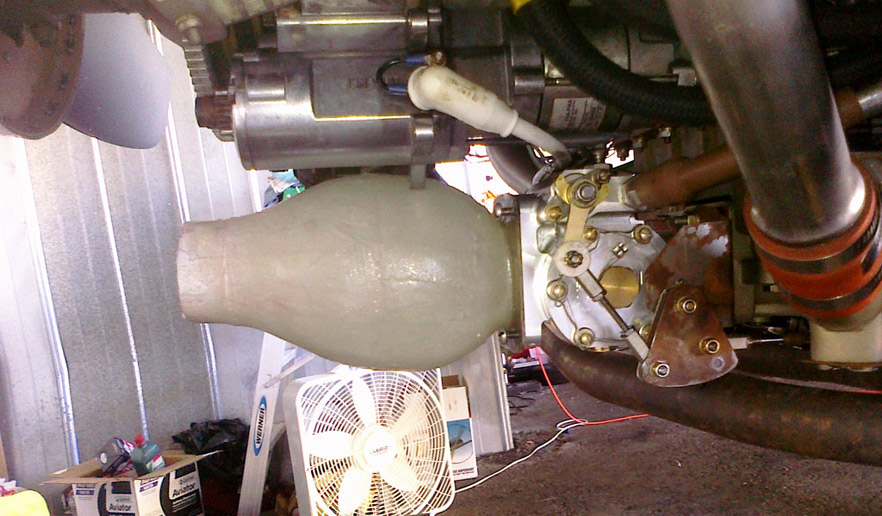
During the original install of this engine, many cowling modifications had to be made. One of those modifications was molding a new air intake for the engine. In the interest of time, that area left a lot of room for improvement. I took it upon myself to create a much more efficient intake and airbox. The previous setup did not allow for any sort of airbox, only a scat tube from the cowl inlet to the fuel servo. For starters, my idea for an airbox involves a diffuser. Same theory as a jet engine I guess.. Inlet size x is increased to size y. This diffuser converts velocity to pressure, or in the engines case, Boost! The idea I had came out looking like a bell shape for the air to convert to pressure, then a funnel to force the high pressure into the fuel servo. Sounded good one night over a few drinks, and the diagrams on the bar napkins were very convincing the next morning..
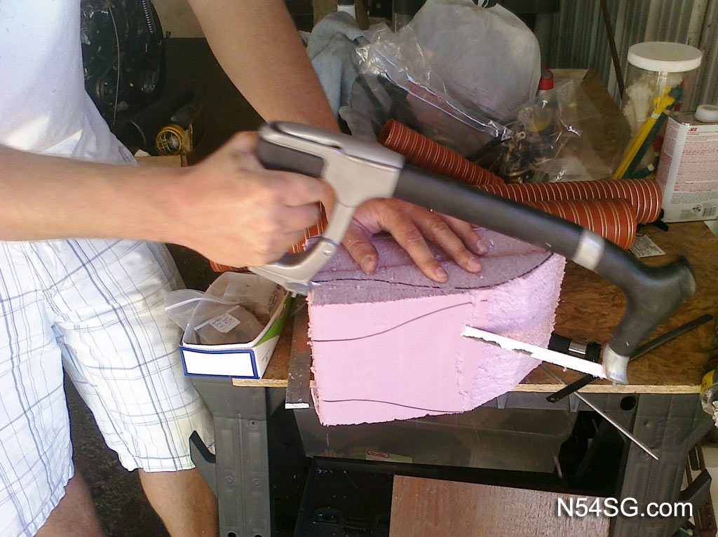
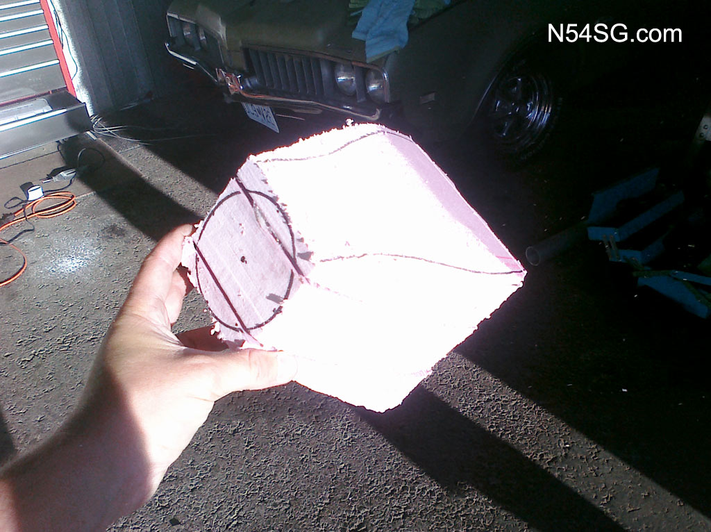
I began by measuring the amount of space available in the cowl, the bigger the y variable the better. That ended up being 6 inch diameter, or 2 times x. 1 to 2 ratio sounds good.. I then mapped a template on cardboard paper to check clearance from the cowl and starter. This same template gave me a guide to use on the outside of the mold, a simple attempt to keep the end product round and uniform. A local stop at an aviation parts store, (Home Depot) netted some polypropylene foam. This foam has 1 key benefit I’ll explain in a second. 3 pieces of 2″ thick foam gave me my 6″ diameter needed for the airbox’ widest point. Next, I drew an outline of my template on all 4 sides of the foam block giving me a basic idea to trim the foam with a hack saw.
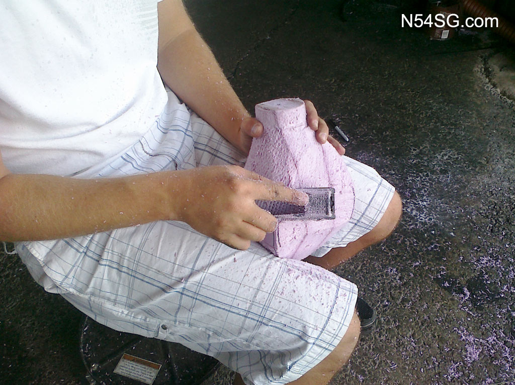
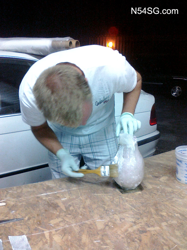
Once I had the basic shape, I sanded it round by hand. Not exactly scientific, but I didn’t have a better way to do it in the interest of time. 3 layers of glass and a few hours later I had a part, that was full of polypropylene foam. Here is the cool part, acetone eats polypropylene foam instantly! So a few drops down the end of the airbox, and out came a runny mess of melted foam on the other end. Worked great! As for power gains? It has not been determined yet.. down low I’m not seeing much of a gain on the old system, but up high I think it is doing its job!
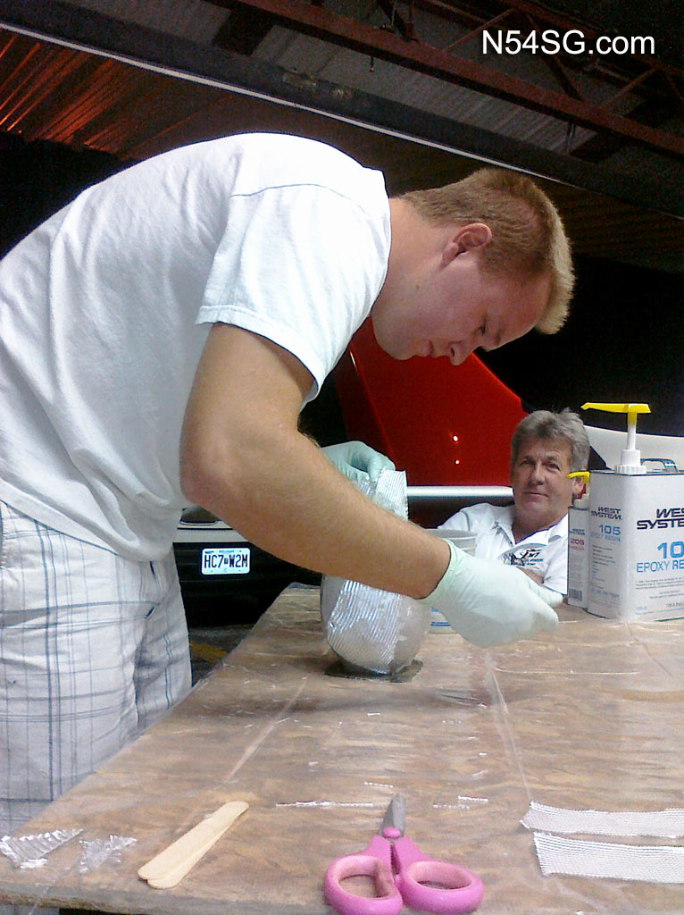
Someone in the background seems like a professional spectator… he must fly one of those aluminum cans. ; )
Thats funny, I assume this is Phil. I think Richard was rather interested in what I was doing in that pic. haha
Wearing my engineering hat for a moment, it appears that the inlet area is the same at both ends of this round box. If that’s the case, there would be no net gain. So, did you actually gain anything with this mod?
I do understand the point, but.. Keep in mind it isn’t an even flow through tube. One end has ram pressure, and the other is a huge vacume. Although I did see some MP gains, I don’t think it was a result of the airbox itself as I went from a 2.5″ inlet to a 3″ inlet at the same time. After some more homework, I found that I do not have the correct divergence angle. It should be way less actually. Something in the order of 7 degrees. In that short disntance (inlet to fuel servo) I wouldn’t see nearly the amount of divergence that I have in the first airbox. V.2 hopefully will be done soon, I doubt before Reno though.
Agree with Danny.
This system seems to be trading air velocity for pressure and back to velocity (minus losses) as the air reaccelerates in the second half of your airbox.
If you were using an air filter enclosed in the airbox then yes, it would help.
Have you considered installing a straight tube of the same diameter to see what happens ?
Yes, sort of. The original setup was a 2.5 tube. Aerodynamics in a tube are less than ideal, worse when the angle of attack of the tube is somewhat of a variable. Although without back to back test data, I can’t say for sure as I changed a few things at one time, not good for measuring gains.
Again, I will point out this isn’t a perfect airbox. In fact I have a much better way to implement the same idea, it is just a matter of time till I do it. Remember, this is ram pressure on one side, and engine intake on the other. Not a simple flow through system. During the Reno Air Races this year, I would consistantly have 26-27″ manifold pressure at a density altitude of 6,000-7,000 ft. So, say what you want but the damn thing works!